
Brake system for a wind turbine with integrated rotor lock, generator and wind turbine

A braking system and generator technology, applied in wind turbine components, control of wind turbines, wind power generation, etc., to achieve the effect of increasing braking efficiency, easy maintenance and repair

Active Publication Date: 2011-06-01
SIEMENS GAMESA RENEWABLE ENERGY AS
View PDF7 Cites 15 Cited by
  • Summary
  • Abstract
  • Description
  • Claims
  • Application Information

AI Technical Summary

Problems solved by technology

However, the proposed solution minimizes the size of the structure and also constrains the size of the brake system, which is not ideal for direct drive wind turbines, where the caliper and brake disc should be sized as much as possible. May be large to withstand large braking torques due to slow rotation of the rotor
The braking system shown in US 2005 / 230979 also blocks access through the generator and makes it impossible to get into the hub from the nacelle / generator

Method used


Image

  • Brake system for a wind turbine with integrated rotor lock, generator and wind turbine
  • Brake system for a wind turbine with integrated rotor lock, generator and wind turbine
  • Brake system for a wind turbine with integrated rotor lock, generator and wind turbine

Examples


Embodiment Construction

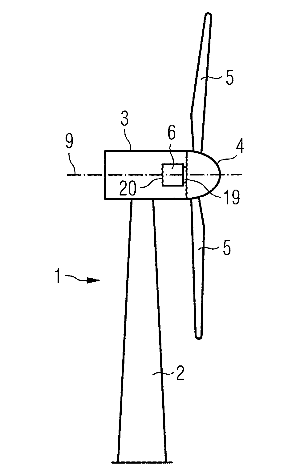
[0045] will now refer to Figure 1-7 Embodiments of the present invention are described. figure 1 A wind turbine 1 is shown schematically. Wind turbine 1 comprises a tower 2 , a nacelle 3 and a hub 4 . Nacelle 3 is located on top of tower 2 . The hub 4 comprises a plurality of wind turbine blades 5 . Hub 4 is mounted to nacelle 3 . Furthermore, the hub 4 is pivotally mounted so that it can rotate about an axis of rotation 9 . The generator 6 is located inside the nacelle 3 . The wind turbine 1 is a direct drive wind turbine. The generator 6 comprises a proximal side 19 facing the hub 4 and a distal side 20 opposite the hub 4 .

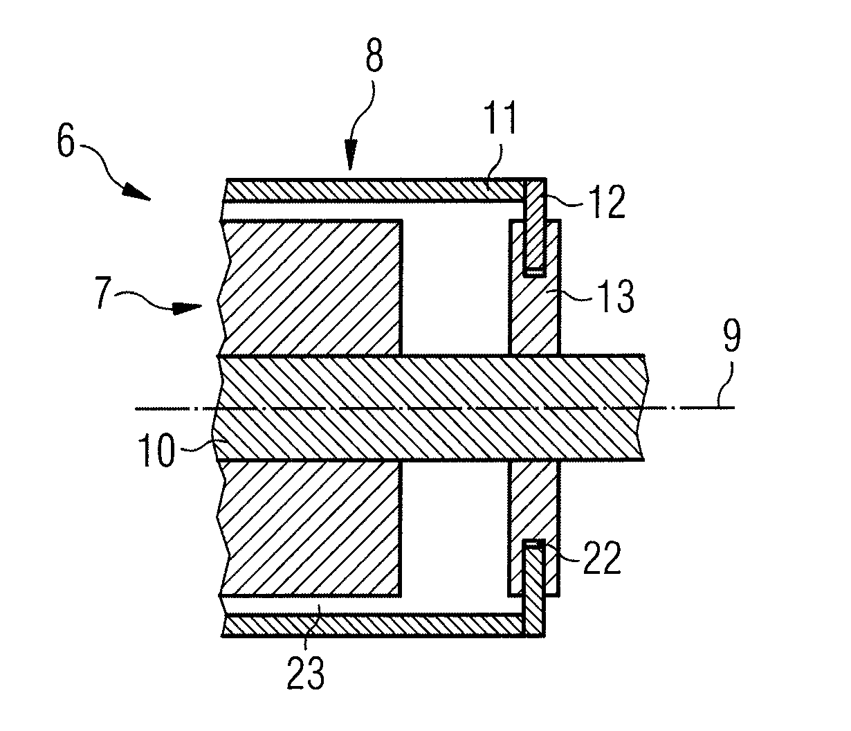
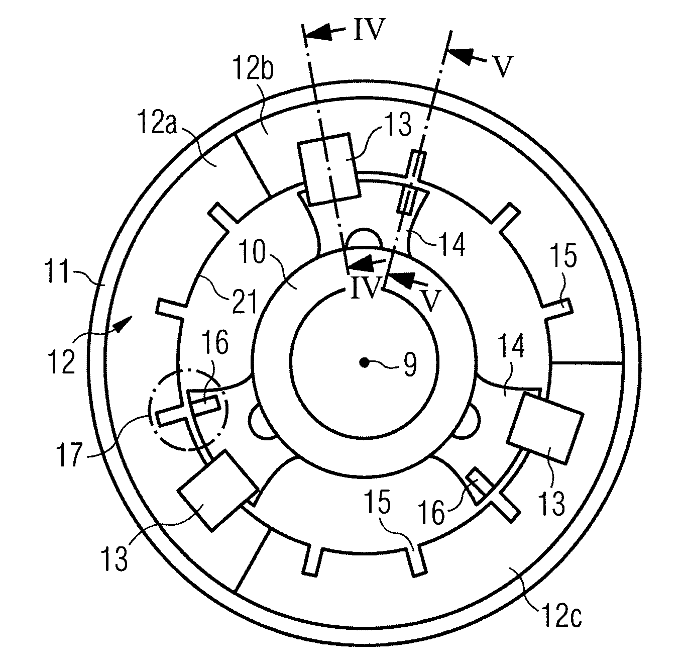
[0046] figure 2 A part of a generator 6 with an external rotor configuration is shown schematically in cross-section. The generator 6 includes a stator assembly 7 and a rotor assembly 8 . The stator assembly 7 includes a fixed shaft 10 positioned close to the axis of rotation 9 . The rotor assembly 8 comprises an outer rotor part 11 positio...


PUM


Abstract

The invention relates to a brake system for a wind turbine with an integrated rotor lock, a generator and a wind turbine. A brake system, especially for a wind turbine generator (6), is provided. The brake system comprises a rotor lock system (17) which is integrated in the brake system.

Description

technical field [0001] The invention relates to a braking system for a wind turbine, in particular a braking system for a generator, as well as a generator and a wind turbine. Background technique [0002] In principle, there are two main types of wind turbines considering their direct drive configuration. A first type of wind turbine is the more traditional type of wind turbine comprising a gearbox arranged between the main shaft of the wind turbine and the generator. A second type of wind turbine is the gearless type, in which the gearbox and the conventional generator are replaced by a multi-pole generator, a so-called direct-drive or directly-driven generator. Such a direct drive generator may be manufactured as a synchronous generator with a wound rotor or with permanent magnets attached to the rotor, or it may be designed as an alternative type generator. One challenge with direct drive generators is the mechanical braking system. The braking system needs to be on t...

Claims


Application Information

Patent Timeline
Patent Type & Authority Applications(China)
IPC IPC(8): F03D7/04H02K7/102H02K7/18F03D9/00F03D1/06
CPCF03D7/0248F03D11/00Y02E10/72Y02E10/723Y02E10/725F03D9/002Y02E10/721Y02E10/722F05B2260/902F03D80/00F03D9/25F05B2260/31
Inventor U·埃里克森J·A·A·文格
Owner SIEMENS GAMESA RENEWABLE ENERGY AS
Learn More