Brake system, generator and wind turbine

a brake system and generator technology, applied in the direction of axially engaging brakes, engine fuctions, dynamo-electric machines, etc., can solve the problems of restricting the size of the brake system and the inability to go into the hub from the nacelle, so as to achieve the effect of convenient maintenance and servi

Active Publication Date: 2011-05-26
SIEMENS GAMESA RENEWABLE ENERGY AS
View PDF12 Cites 19 Cited by
  • Summary
  • Abstract
  • Description
  • Claims
  • Application Information

AI Technical Summary

Benefits of technology

[0009]The inventive brake system has the advantage, that the brake disc can be mounted on a cylindrical support structure of an outer rotor. In this case the possible large diameter of the machine can be fully used in order to use a brake disc with largest possible diameter. This increases the efficiency of the brake. Moreover, a bigger brake disc and bigger brake callipers can be used which provides a larger effective contact surface. A large effective contact surface is necessary in order to maintain the rotor in a parking position, for example. A further advantage is that more heat can be absorbed and distributed in a large brake disc compared with smaller brake discs.
[0022]Furthermore, the brake disc may comprise a number of radial segments. If the brake disc is divided into radial segments it is possible to exchange a large brake disc in an easy way.
[0026]Rotor elements and stator elements are typically arranged opposite to each other, thus the air gap has to ensure that they do not come into contact while the generator is at operation. Thus the air gap should be very small to ensure the efficiency of the generator on the one hand while a certain width of the air gap is needed to prevent mechanical damages.
[0030]If the radial distance between the brake disc and the frictional member is less than the radial distance between the rotor and the stator, the brake disc would hit the frictional member, for example the bracket of the brake calliper system, before the stator hits the rotor. This prevents damages to the generator and increases the safety of the system. The radial distance between rotor and stator is also called air gap. The generator may be part of a direct drive wind turbine with a unilateral bearing. The generator may comprises an unsupported end, which is the opposite end of where the bearing is located. By means of the inventive generator the air gap at the unsupported end can be maintained within the narrow tolerances.
[0034]Since the inventive brake system may be more or less an integrated part of the generator it does not take up extra space inside the nacelle. Moreover, entrance through the generator, especially through the stator, is possible, which is a great advantage. This provides easy access to the hub. Moreover, easy access to the parts of the brake system, especially if the brake system is located at the far side of the generator opposite to the hub, is provided. This allows for easier maintenance and service.

Problems solved by technology

One of the challenges with the direct drive generator is the mechanical brake system.
However, the proposed solution minimizes the size of the construction and also restricts the size of the brake system which is unwanted for a direct drive wind turbine where the size of the callipers and the brake disc should be as big as possible in order to withstand the high braking moments due to the slow rotational speed of the rotor.
The brake system shown in US 2005 / 230979 also prevents passage though the generator and it is not possible to go into the hub from the nacelle / generator.

Method used


Image

  • Brake system, generator and wind turbine
  • Brake system, generator and wind turbine
  • Brake system, generator and wind turbine

Examples


Embodiment Construction

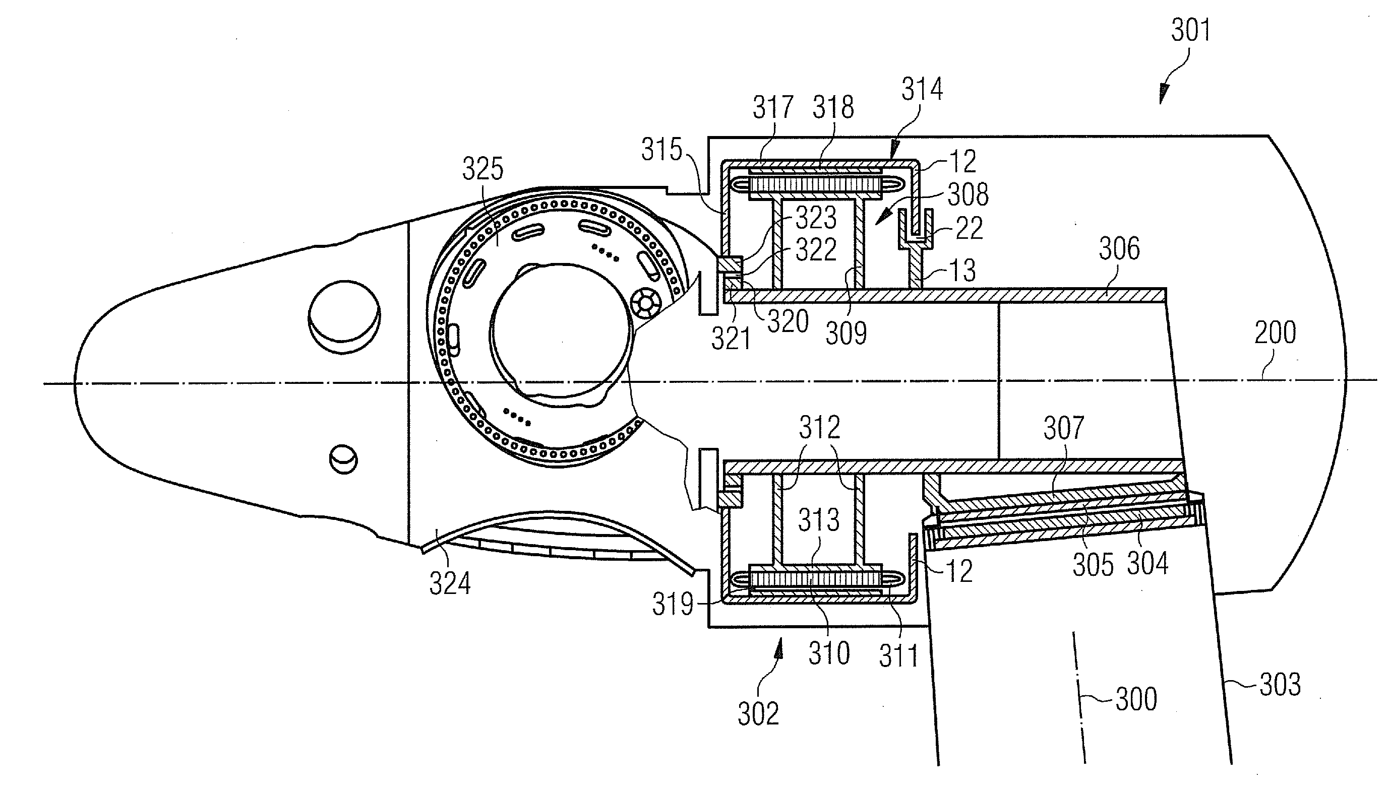
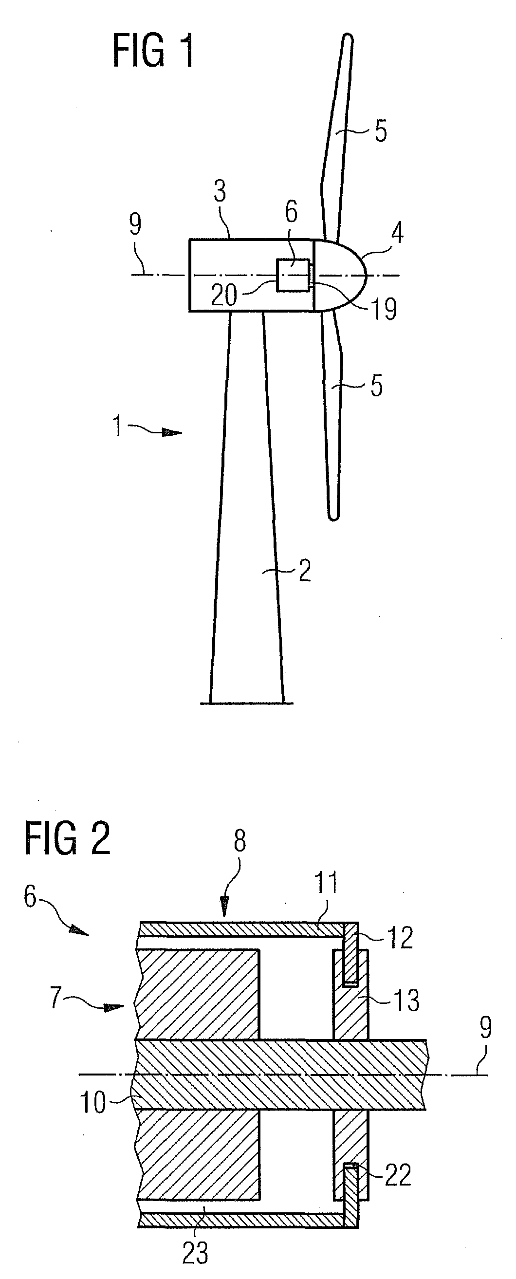
[0043]An embodiment of the present invention will now be described with reference to FIGS. 1 to 7. FIG. 1 schematically shows a wind turbine 1. The wind turbine 1 comprises a tower 2, a nacelle 3 and a hub 4. The nacelle 3 is located on top of the tower 2. The hub 4 comprises a number of wind turbine blades 5. The hub 4 is mounted to the nacelle 3. Moreover, the hub 4 is pivot-mounted such that it is able to rotate about a rotation axis 9. A generator 6 is located inside the nacelle 3. The wind turbine 1 is a direct drive wind turbine. The generator 6 comprises a near side 19 facing the hub 4 and a far side 20 opposite to the hub 4.

[0044]FIG. 2 schematically shows part of a generator 6 with an outer rotor configuration in a sectional view. The generator 6 comprises a stator assembly 7 and a rotor assembly 8. The stator assembly 7 comprises a stationary shaft 10 which is located close to the rotation axis 9. The rotor assembly 8 comprises an outer rotor portion 11 which is located ra...


PUM


Abstract

A brake system, especially for a generator, including a rotor assembly, a stator assembly and a rotation axis is disclosed. The rotor assembly includes an outer portion which is located radially outward of the stator assembly. The outer portion includes a brake disc, and the stator assembly comprises at least one frictional member operatively configured for frictionally engaging at least a portion of the brake disc.

Description

CROSS REFERENCE TO RELATED APPLICATIONS[0001]This application claims priority of European Patent Office application No. 09014766.1 EP filed Nov. 26, 2009, which is incorporated by reference herein in its entirety.FIELD OF INVENTION[0002]The invention relates to a brake system, especially for a generator, a generator, especially a direct drive generator, and a wind turbine.BACKGROUND OF INVENTION[0003]In principle there are two main types of wind turbines in view of the direct drive configuration of a wind turbine. The first type of a wind turbine is the more classical type of a wind turbine comprising a gearbox arranged between a main shaft and a generator of the wind turbine. The second type of a wind turbine is a gearless type, where the gearbox and the conventional generator are substituted by a multipolar generator, a so called direct drive or directly driven generator. Such a direct drive generator can be made as a synchronous generator with winded rotor or with permanent magne...

Claims


Application Information

Patent Timeline
Patent Type & Authority Applications(United States)
IPC IPC(8): F03D9/00F16D55/22F03D11/00F16D63/00H02K7/102
CPCF03D7/0248F03D9/002F03D11/00F05B2260/902H02K7/102Y02E10/723Y02E10/721Y02E10/722Y02E10/725H02K2213/12H02K7/1838F03D9/25F03D80/00F05B2260/31Y02E10/72F03D80/70F03D80/88
Inventor ERIKSEN, UFFEVENG, JENS ANTON AGERSKOV
Owner SIEMENS GAMESA RENEWABLE ENERGY AS
Why Eureka
Try Eureka