Stirling engine

a technology of rotating engine and rotating shaft, which is applied in the direction of engine components, hot gas positive displacement engine plants, machines/engines, etc., to achieve the effects of low pressure drop, high thermal stability and fatigue strength, and efficient heat exchang

Active Publication Date: 2021-02-25
MASTON
View PDF0 Cites 0 Cited by
  • Summary
  • Abstract
  • Description
  • Claims
  • Application Information

AI Technical Summary

Benefits of technology

[0012]It is an object of the present invention to present a Stirling engine that has a regenerator that is capable of performing efficient heat exchange with the working gas and that has a high thermal stability

Problems solved by technology

Accordingly it is a challenge to design a reg

Method used


Image

  • Stirling engine
  • Stirling engine
  • Stirling engine

Examples


Embodiment Construction

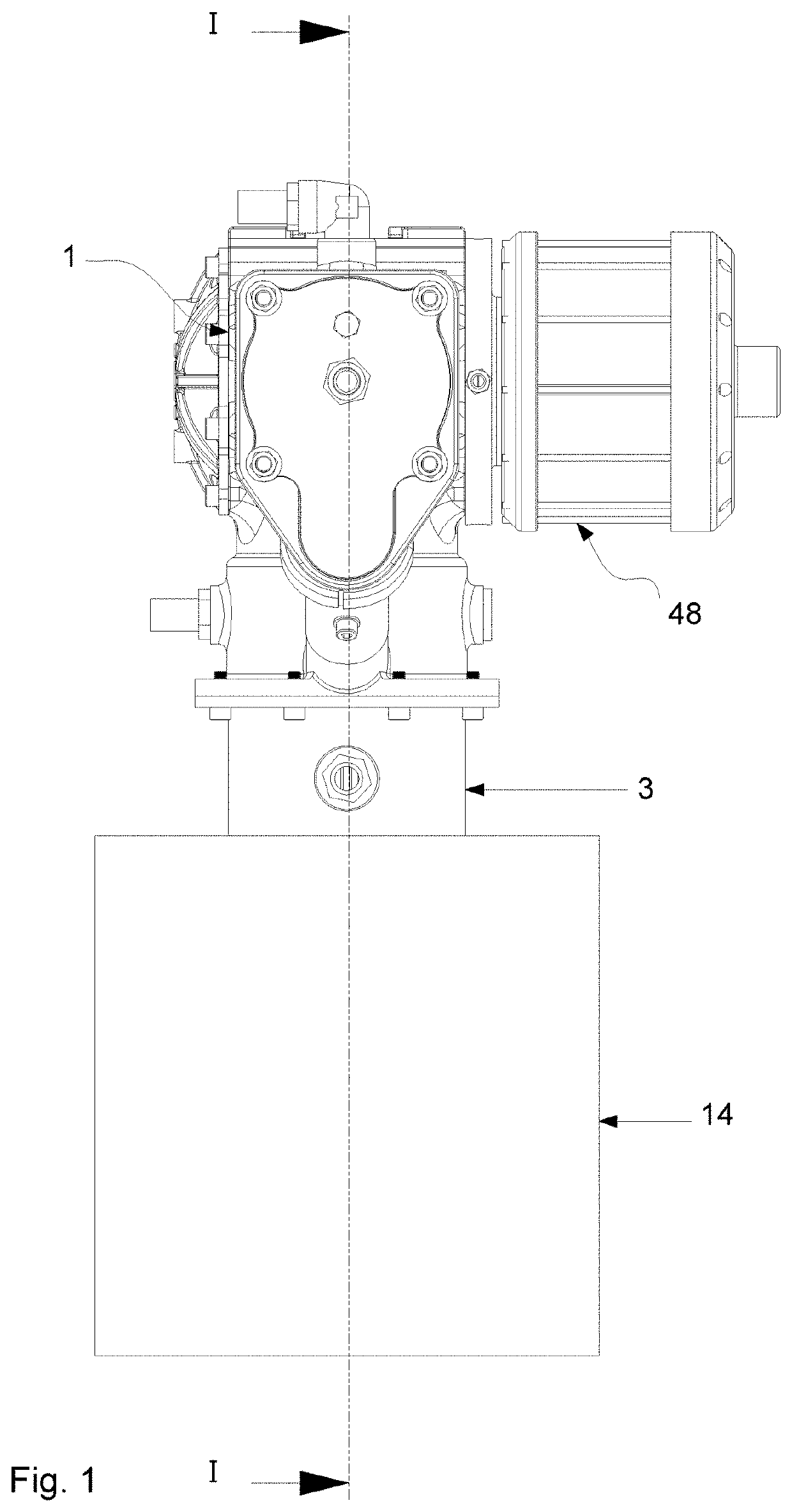
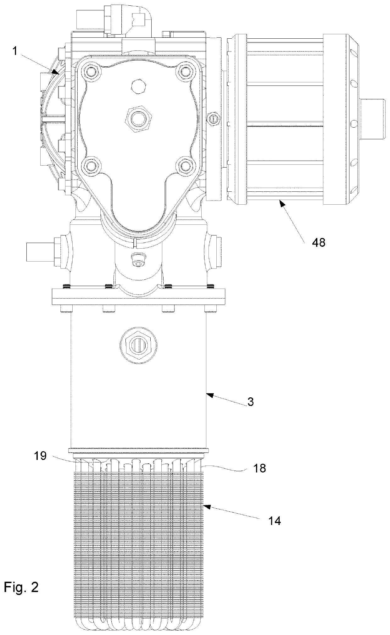
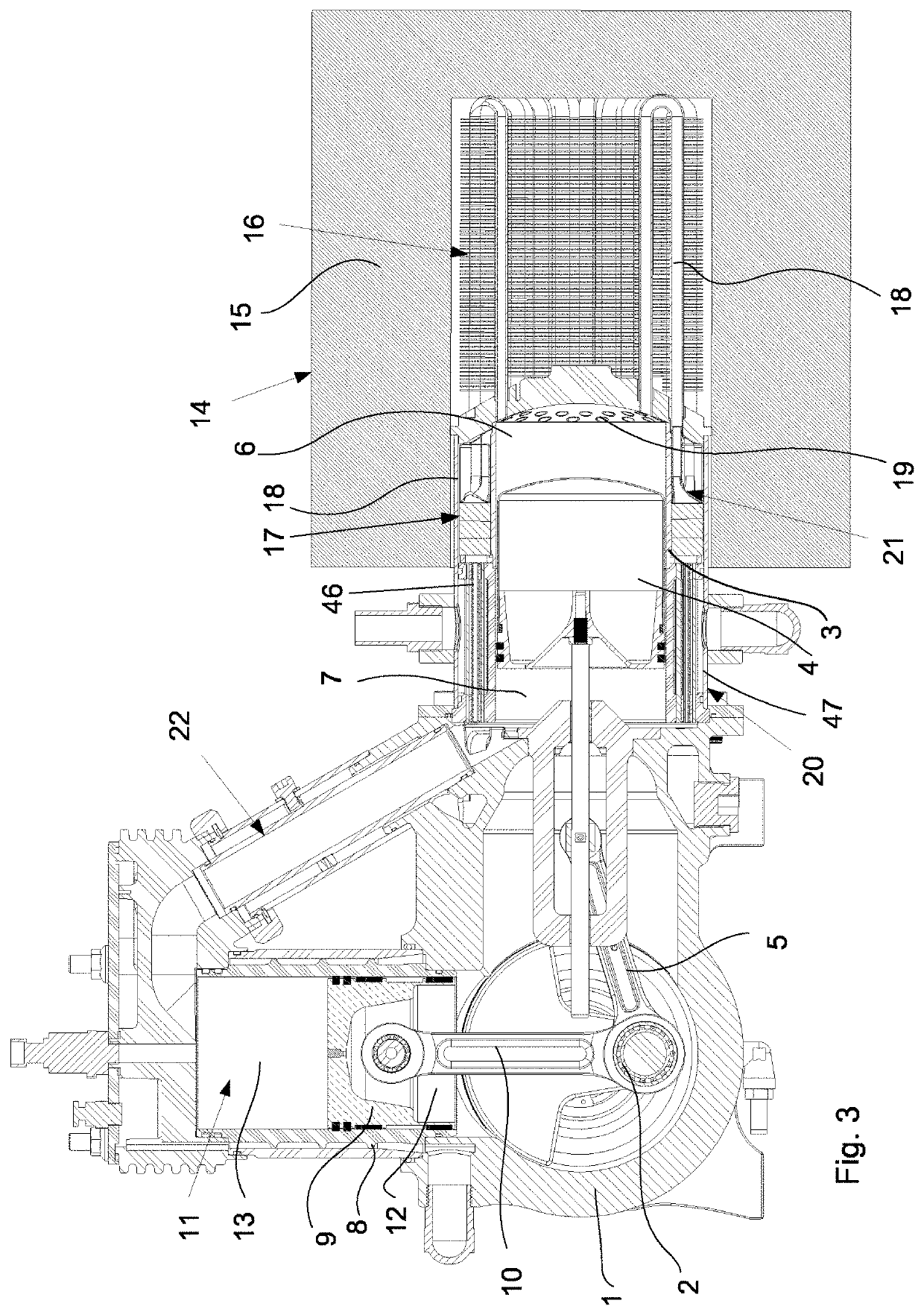
[0033]FIGS. 1-3 show an example of a Stirling engine according to the present disclosure. The Stirling engine shown is of gamma type and comprises a crank case 1 with a crank shaft 2 arranged therein, and a displacer cylinder 3 with a reciprocatingly arranged displacer piston 4 therein. The displacer piston 4 is connected to the crank shaft 2 via a connecting rod 5 extending through a first end of said displacer cylinder 3. During operation of the Stirling engine, the displacer cylinder 3 defines a hot chamber 6 and a cool chamber 7 separated by the displacer piston 4.

[0034]The Stirling engine further comprises a working cylinder 8 with a reciprocatingly arranged working piston 9 therein, said working piston 9 being connected to the crank shaft 2 via a connecting rod 10 extending through a first end of the working cylinder 8. A working cylinder chamber 11 defined by the working cylinder 8 is divided by the working piston 9 into a first part 12, through which said connecting rod 10 e...


PUM


Abstract

A Stirling engine comprising:
    • a crank case (1) with a crank shaft (2) arranged therein,
    • a displacer cylinder (3) with a reciprocatingly arranged displacer piston (4) therein, said displacer piston (4) being connected to said crank shaft (2) via a connecting rod (5) extending through a first end of said displacer cylinder (3), and wherein the displacer cylinder (3) defines a hot chamber (6) and a cool chamber (7) separated by the displacer piston (4),
    • a working cylinder (8) defining a working cylinder chamber (11) with a reciprocatingly arranged working piston (9) therein, said working piston (9) being connected to said crank shaft (2) via a connecting rod (10) extending through a first end of the working cylinder (8),
    • a heater device (14), arranged at a second end of said displacer cylinder (3) opposite to said first end and configured to heat a working gas which is present in the hot chamber (6) of the displacer cylinder (3) and in fluid communication with the working cylinder chamber (11) through a working gas channel which comprises
    • a first heat exchanger (16) extending from a head (19) of the displacer cylinder (3) into the heater device (14), and
    • a second heat exchanger (17) formed by a regenerator arranged outside the heater device (14). The regenerator (17) comprises a regenerator element (17) formed by metal foam that has an open porosity.

Description

TECHNICAL FIELD[0001]The present invention relates to a Stirling engine comprising:[0002]a crank case with a crank shaft arranged therein,[0003]a displacer cylinder with a reciprocatingly arranged displacer piston therein, said displacer piston being connected to said crank shaft via a connecting rod extending through a first end of said displacer cylinder, and wherein the displacer cylinder defines a hot chamber and a cool chamber separated by the displacer piston,[0004]a working cylinder defining a working cylinder chamber with a reciprocatingly arranged working piston therein, said working piston being connected to said crank shaft via a connecting rod extending through a first end of the working cylinder,[0005]a heater device, arranged at a second end of said displacer cylinder opposite to said first end and configured to heat a working gas which is present in the hot chamber of the displacer cylinder and in fluid communication with the working cylinder chamber through a working...

Claims


Application Information

Patent Timeline
IPC IPC(8): F02G1/057
CPCF02G1/057F02G2257/00F02G1/043
Inventor MASTONSTRÅLE, STEFAN
Owner MASTON
Why Eureka
Try Eureka