Stirling engine comprising metal foam regenerator

a metal foam and engine technology, applied in the direction of engines, machines/engines, hot gas positive displacement engine plants, etc., to achieve the effects of low pressure drop, high thermal stability and fatigue strength, and efficient heat exchang

Active Publication Date: 2022-03-01
MASTON
View PDF14 Cites 0 Cited by
  • Summary
  • Abstract
  • Description
  • Claims
  • Application Information

AI Technical Summary

Benefits of technology

[0013]It is an object of the present invention to present a Stirling engine that has a regenerator that is capable of performing efficient heat exchange with the working gas and that has a high thermal stability and fatigue strength, is rigid such that it does not get compressed when subjected the pressures that it can be assumed to be subjected to, and that results in a relatively low pressure drop over the regenerator.
[0014]The regenerator should also be of a design that promotes non-complicated mounting and exchange thereof.
[0016]Metal foam has the advantage of being a material that, thanks to its chemical and geometrical constitution, can both be very efficient as heat transceiver and have a very high mechanical strength. The metal may be any metal or metal alloy suitable for use in a high temperature application as a heat exchanging material, such as a ferro chrome alloy or nickel steel. Metal foam can be provided with an open porosity in which the pore size is very small, thereby generating a large effective contact surface for the working gas to exchange heat through. The metal foam may be referred to as open celled metal foam, also called metal sponge. Preferably, the regenerator element has been produced by means of a sintering process in which such porosity is obtainable. A foam of a solid polymer may be used in the process in order to form a skeleton on which the powder mixture to be sintered is adhered before sintering takes place. The provision of an open porosity will provide for a very efficient heat exchange as well as advantageous flow conditions for the working gas.
[0019]According to one aspect, the metal foam is comprised by a matrix, wherein the matrix material in itself is at least partly hollow. Thereby, there is a closed porosity in the metal foam, wherein the pores of the closed porosity are found inside the matrix material. Such porosity improves the heat exchanging capacity of the metal foam in the sense that rapid exchange of heat can be achieved without the matrix adopting too much heat. According to one aspect, the matrix is formed by interconnected threads of metal that have an average thickness in the region of 10-100 μm, 20-40 μm or 20-25 μm. At least some of the threads are hollow, i.e. have a closed porosity, which results in the above-mentioned closed porosity of the matrix. The hollowness may for example be achieved by means of a production process in which foam of a polymer, having the geometry of the metal foam to be formed, is formed in a mould in a first stage. Thereafter, the open porosity is filled with a suitable material such as plaster. Thereafter, molten metal is introduced into the body, thereby melting down the polymer matrix and taking the place of the latter. The plaster is removed, leaving a remaining open porosity in the formed body. By controlling process parameters such as choice of polymer, choice of metal, metal filling rate, cooling rate etc., the solidification of the metal and the replacement of polymer with metal can be controlled such that the requested degree of hollowness is achieved.
[0023]According to one aspect, the regenerator element has lower hydraulic porosity in an end thereof turned towards the displacer cylinder than in an end thereof turned towards the working cylinder. Thereby, the part of the regenerator element that is subjected to higher temperature is mechanically stronger the parts thereof that will be subjected to less severe combinations of gas pressure changes and high temperature.
[0024]According to one aspect, the regenerator element has lower matrix porosity in an end thereof turned towards the displacer cylinder than in an end thereof turned towards the working cylinder. Thereby, the regenerator element has an increased heat absorption capacity in the region where the largest heat fluctuations and temperatures will occur.

Problems solved by technology

Accordingly it is a challenge to design a regenerator that fulfils all these requirements.

Method used


Image

  • Stirling engine comprising metal foam regenerator
  • Stirling engine comprising metal foam regenerator
  • Stirling engine comprising metal foam regenerator

Examples


Embodiment Construction

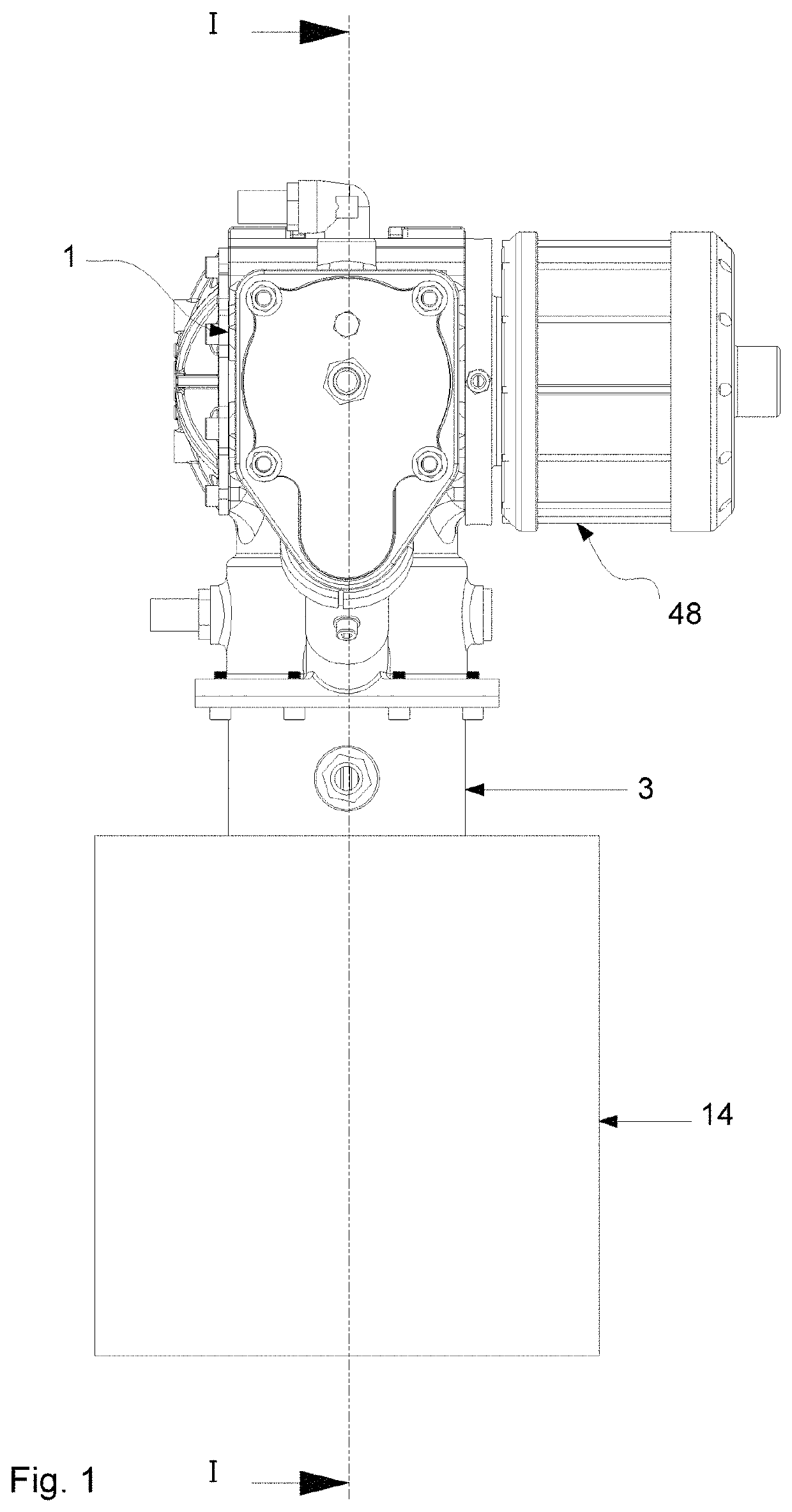
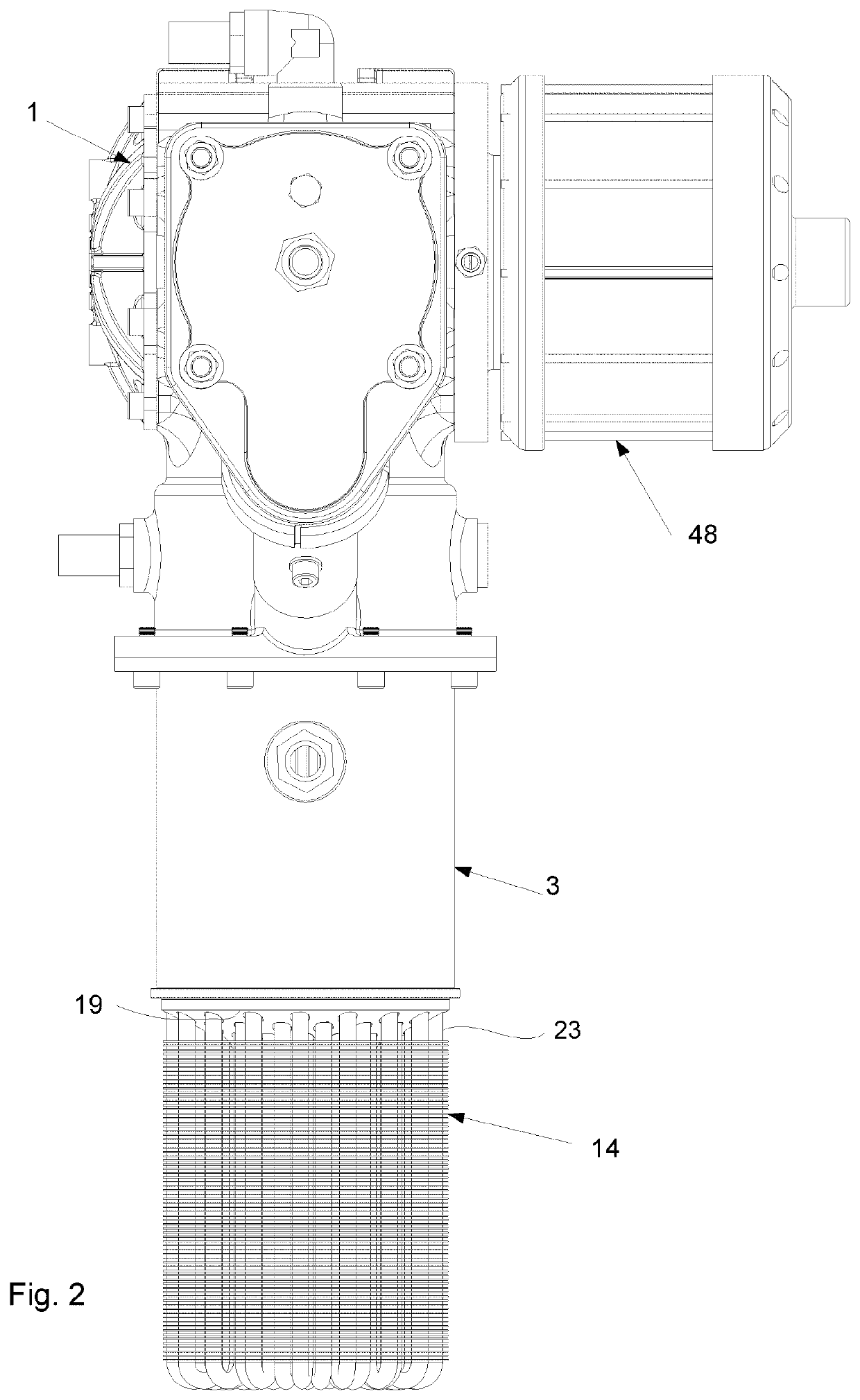
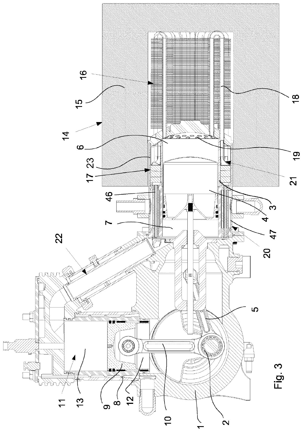
[0034]FIGS. 1-3 show an example of a Stirling engine according to the present disclosure. The Stirling engine shown is of gamma type and comprises a crank case 1 with a crank shaft 2 arranged therein, and a displacer cylinder 3 with a reciprocatingly arranged displacer piston 4 therein. The displacer piston 4 is connected to the crank shaft 2 via a connecting rod 5 extending through a first end of said displacer cylinder 3. During operation of the Stirling engine, the displacer cylinder 3 defines a hot chamber 6 and a cool chamber 7 separated by the displacer piston 4.

[0035]The Stirling engine further comprises a working cylinder 8 with a reciprocatingly arranged working piston 9 therein, said working piston 9 being connected to the crank shaft 2 via a connecting rod 10 extending through a first end of the working cylinder 8. A working cylinder chamber 11 defined by the working cylinder 8 is divided by the working piston 9 into a first part 12, through which said connecting rod 10 e...


PUM


Abstract

A Stirling engine comprising:a crank case (1) with a crank shaft (2) arranged therein,a displacer cylinder (3) with a reciprocatingly arranged displacer piston (4) therein, said displacer piston (4) being connected to said crank shaft (2) via a connecting rod (5) extending through a first end of said displacer cylinder (3), and wherein the displacer cylinder (3) defines a hot chamber (6) and a cool chamber (7) separated by the displacer piston (4),a working cylinder (8) defining a working cylinder chamber (11) with a reciprocatingly arranged working piston (9) therein, said working piston (9) being connected to said crank shaft (2) via a connecting rod (10) extending through a first end of the working cylinder (8),a heater device (14), arranged at a second end of said displacer cylinder (3) opposite to said first end and configured to heat a working gas which is present in the hot chamber (6) of the displacer cylinder (3) and in fluid communication with the working cylinder chamber (11) through a working gas channel which comprisesa first heat exchanger (16) extending from a head (19) of the displacer cylinder (3) into the heater device (14), anda second heat exchanger (17) formed by a regenerator arranged outside the heater device (14). The regenerator (17) comprises a regenerator element (17) formed by metal foam that has an open porosity.

Description

CROSS-REFERENCE TO RELATED APPLICATIONS[0001]This application is the U.S. National Phase under 35. U.S.C. § 371 of International Application PCT / SE2018 / 051352, filed Dec. 20, 2018, which claims priority to Swedish Patent Application No. 1850003-3, filed Jan. 2, 2018. The disclosures of the above-described applications are hereby incorporated by reference in their entirety.TECHNICAL FIELD[0002]The present invention relates to a Stirling engine comprising:[0003]a crank case with a crank shaft arranged therein,[0004]a displacer cylinder with a reciprocatingly arranged displacer piston therein, said displacer piston being connected to said crank shaft via a connecting rod extending through a first end of said displacer cylinder, and wherein the displacer cylinder defines a hot chamber and a cool chamber separated by the displacer piston,[0005]a working cylinder defining a working cylinder chamber with a reciprocatingly arranged working piston therein, said working piston being connected...

Claims


Application Information

Patent Timeline
Patent Type & Authority Patents(United States)
IPC IPC(8): F02G1/057F02G1/043
CPCF02G1/057F02G1/043F02G2257/00
Inventor MASTONSTRÅLE, STEFAN
Owner MASTON
Why Eureka
Try Eureka