
Brake system for a wind turbine with integrated rotor lock generator and wind turbine

a technology of rotor lock generator and brake system, which is applied in the direction of wind energy generation, mechanical equipment, machines/engines, etc., can solve the problems of restricting the size of the brake system and the inability to go into the hub from the nacelle, so as to achieve the effect of convenient maintenance and servi

Active Publication Date: 2014-06-03
SIEMENS GAMESA RENEWABLE ENERGY AS
View PDF11 Cites 1 Cited by
  • Summary
  • Abstract
  • Description
  • Claims
  • Application Information

AI Technical Summary

Benefits of technology

The patent describes a brake system for a wind turbine generator, which is designed to increase safety and efficiency. The brake system is integrated with the generator, which means it takes up minimal space and is easy to maintain. The brake disc can be mounted on a cylindrical support structure of the outer rotor, which ensures efficient braking. The brake disc can also be easily replaced without needing to replace the entire brake system. The brake system prevents damage to the generator and ensures a small air gap between the rotor and stator to maintain efficiency. Access to the brake system and generator is easy, making maintenance and service more convenient. Overall, the brake system improves safety and efficiency without adding extra space or complexity to the wind turbine.

Problems solved by technology

One of the challenges with the direct drive generator is the mechanical brake system.
However, the proposed solution minimizes the size of the construction and also restricts the size of the brake system which is unwanted for a direct drive wind turbine where the size of the callipers and the brake disc should be as big as possible in order to withstand the high braking moments due to the slow rotational speed of the rotor.
The brake system shown in US 2005 / 230979 also prevents passage though the generator and it is not possible to go into the hub from the nacelle / generator.

Method used


Image

  • Brake system for a wind turbine with integrated rotor lock generator and wind turbine
  • Brake system for a wind turbine with integrated rotor lock generator and wind turbine
  • Brake system for a wind turbine with integrated rotor lock generator and wind turbine

Examples


Embodiment Construction

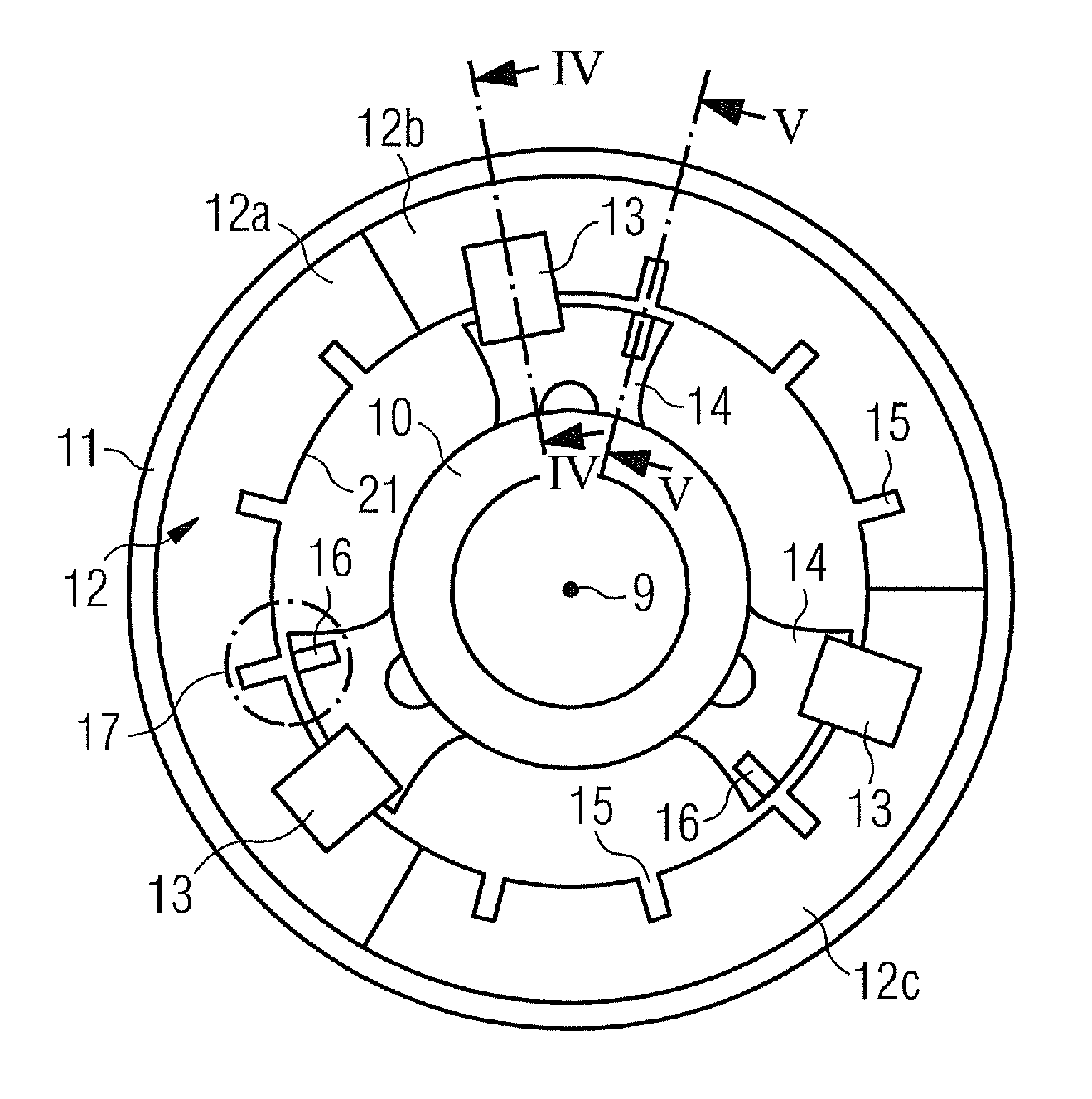
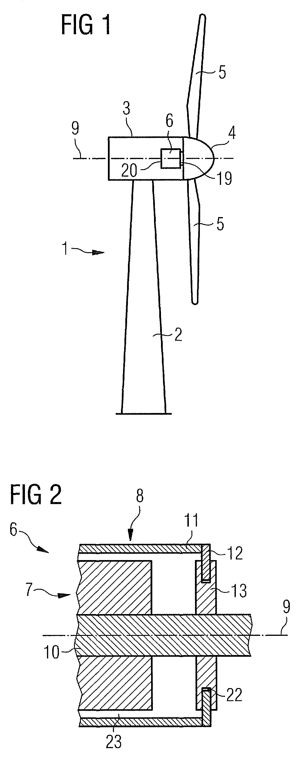
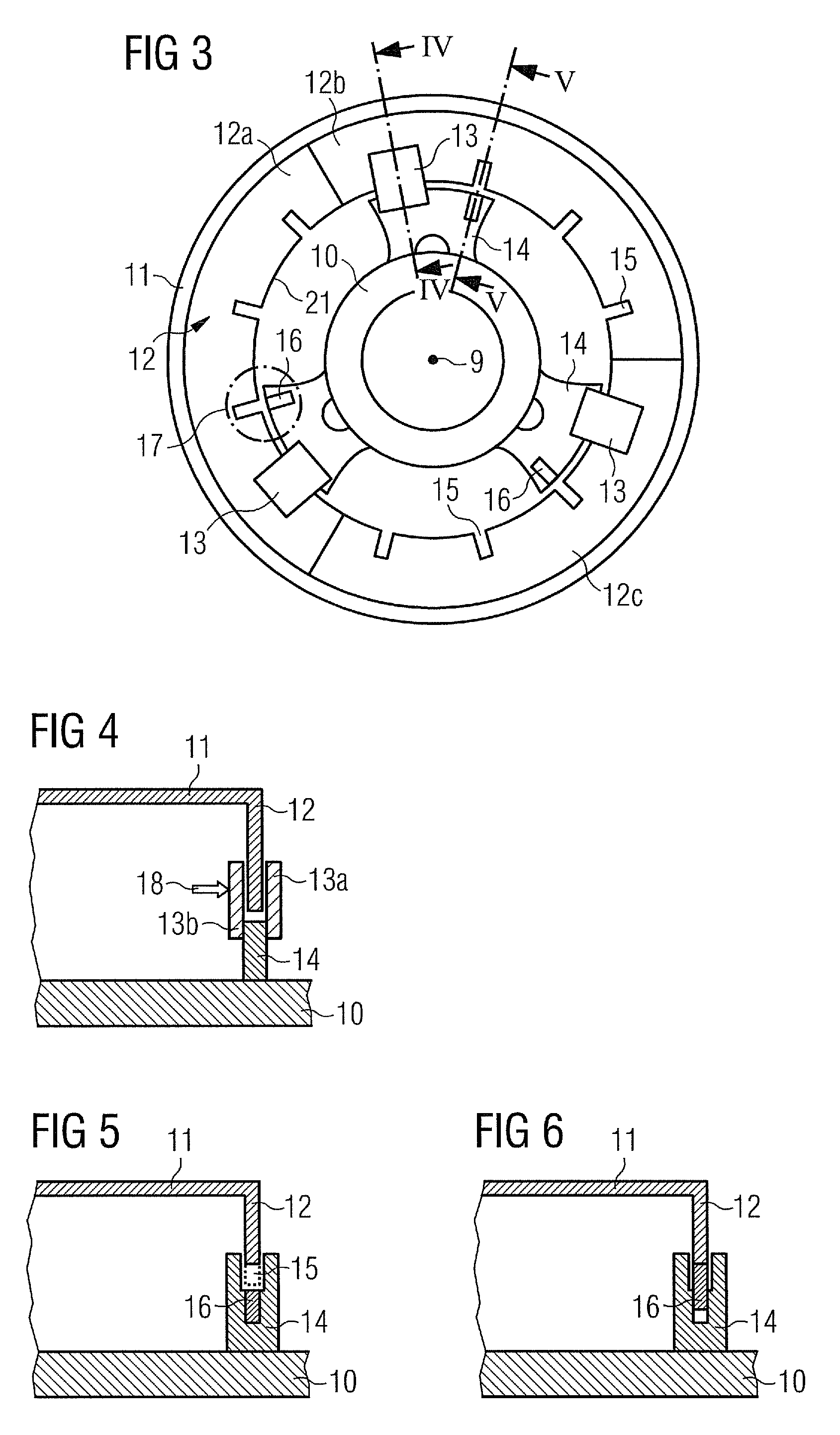
[0046]An embodiment of the present invention will now be described with reference to FIGS. 1 to 7. FIG. 1 schematically shows a wind turbine 1. The wind turbine 1 comprises a tower 2, a nacelle 3 and a hub 4. The nacelle 3 is located on top of the tower 2. The hub 4 comprises a number of wind turbine blades 5. The hub 4 is mounted to the nacelle 3. Moreover, the hub 4 is pivot-mounted such that it is able to rotate about a rotation axis 9. A generator 6 is located inside the nacelle 3. The wind turbine 1 is a direct drive wind turbine. The generator 6 comprises a near side 19 facing the hub 4 and a far side 20 opposite to the hub 4.

[0047]FIG. 2 schematically shows part of a generator 6 with an outer rotor configuration in a sectional view. The generator 6 comprises a stator assembly 7 and a rotor assembly 8. The stator assembly 7 comprises a stationary shaft 10 which is located close to the rotation axis 9. The rotor assembly 8 comprises an outer rotor portion 11 which is located ra...


PUM


Abstract

A brake system for a wind turbine with integrated rotor lock, generator and wind turbine are disclosed. The brake system includes a rotor lock system which is integrated in the brake system. One embodiment includes an actuator such as a hydraulic cylinder. Another embodiment includes a rotor assembly with a brake disc.

Description

CROSS REFERENCE TO RELATED APPLICATIONS[0001]This application claims priority of European Patent Office application No. 09014765.3 EP filed Nov. 26, 2009, which is incorporated by reference herein in its entirety.FIELD OF INVENTION[0002]The invention relates to a brake system for a wind turbine, especially for a generator, a generator and a wind turbine.BACKGROUND OF INVENTION[0003]In principle there are two main types of wind turbines in view of the direct drive configuration of a wind turbine. The first type of a wind turbine is the more classical type of a wind turbine comprising a gearbox arranged between a main shaft and a generator of the wind turbine. The second type of a wind turbine is a gearless type, where the gearbox and the conventional generator are substituted by a multipolar generator, a so called direct drive or directly driven generator. Such a direct drive generator can be made as a synchronous generator with winded rotor or with permanent magnets attached to the ...

Claims


Application Information

Patent Timeline
Patent Type & Authority Patents(United States)
IPC IPC(8): F03D11/02
CPCF05B2260/902Y02E10/723Y02E10/725Y02E10/721F03D11/00F03D9/002F03D7/0248Y02E10/722F03D80/00F03D9/25Y02E10/72F05B2260/31
Inventor ERIKSEN, UFFEVENG, JENS ANTON AGERSKOV
Owner SIEMENS GAMESA RENEWABLE ENERGY AS
Learn More