
Flash control method and device

A control method and a technology of a control device, applied in the digital field, can solve the problems of unable to adjust the amount of flash, destroying the color temperature of the environment, wasting electric energy of shooting equipment, etc.

Inactive Publication Date: 2011-06-01
HUAWEI DEVICE CO LTD
View PDF3 Cites 38 Cited by
  • Summary
  • Abstract
  • Description
  • Claims
  • Application Information

AI Technical Summary

Problems solved by technology

[0005] In the process of realizing the above-mentioned strobe light flashing, the inventor found at least the following problems in the prior art: the strobe light is a high-current device, and if only a small amount of strobe light is required, the strobe light still performs a fixed amount of strobe light, and cannot Adjust the amount of flash, which will waste the power of the shooting equipment, and at this time, the color temperature of the environment will be destroyed due to the opening of the flash, which will affect the white balance of the camera.

Method used


Image

  • Flash control method and device
  • Flash control method and device
  • Flash control method and device

Examples


Embodiment 1

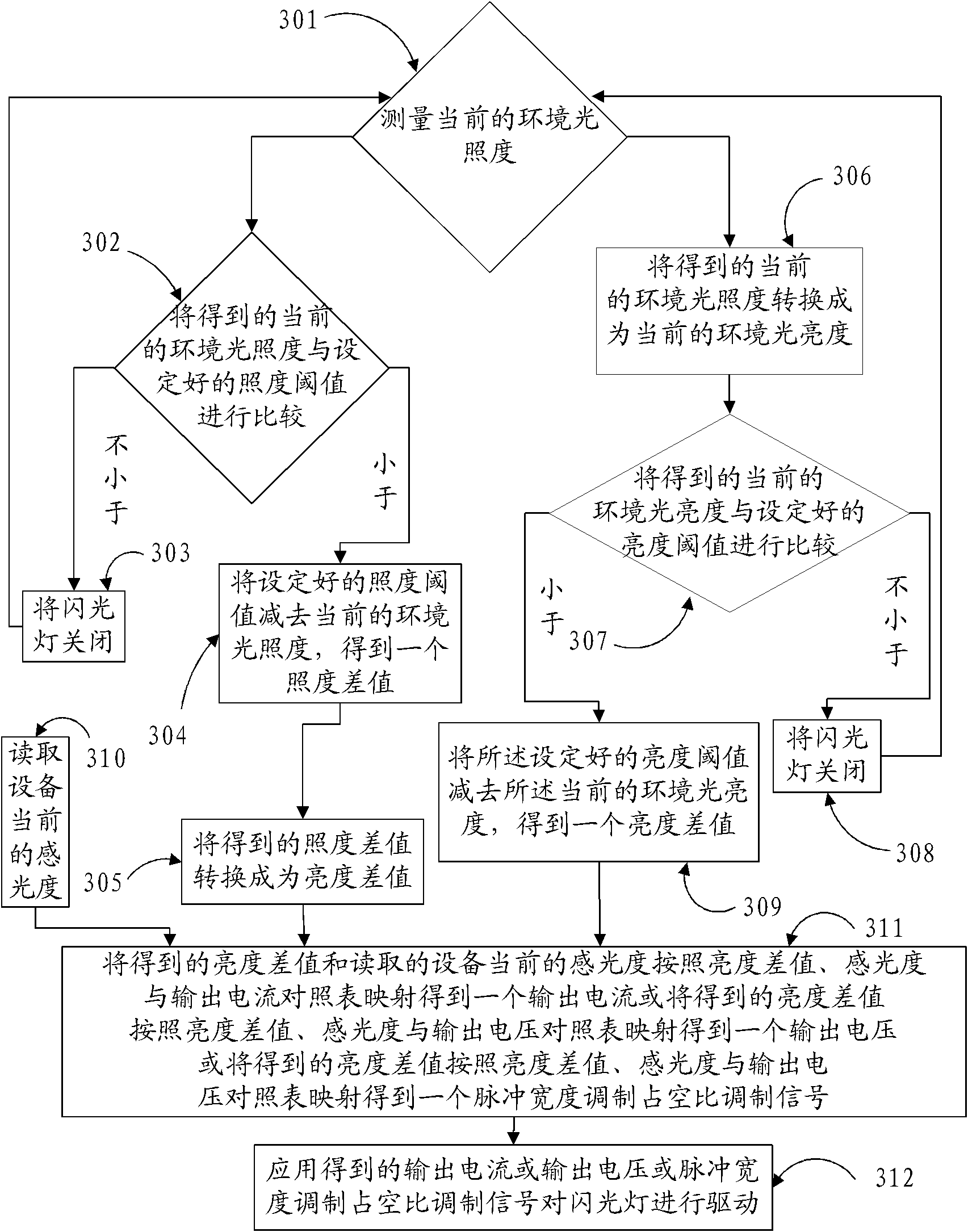
[0037]The embodiment of the present invention provides a flash control method. In the embodiment of the present invention, a lighting condition is preset, and the specific lighting condition can be set according to needs. If the lighting condition is set to the minimum value, Correspondingly, the flash is turned off. The setting of the lighting condition can be completed by reading a pre-configured configuration table, and the process is to read a corresponding value in the pre-configured configuration table. There is at least one value in the configuration table, and when the value in the configuration table is more than one, the number of values ​​between the minimum value and the maximum value in the configuration table can be configured according to the actual situation, and the number of values ​​between the minimum value and the maximum value It is an integer from zero to positive infinity, and the interval from the minimum value to the maximum value and the values ​​bet...

Embodiment 2

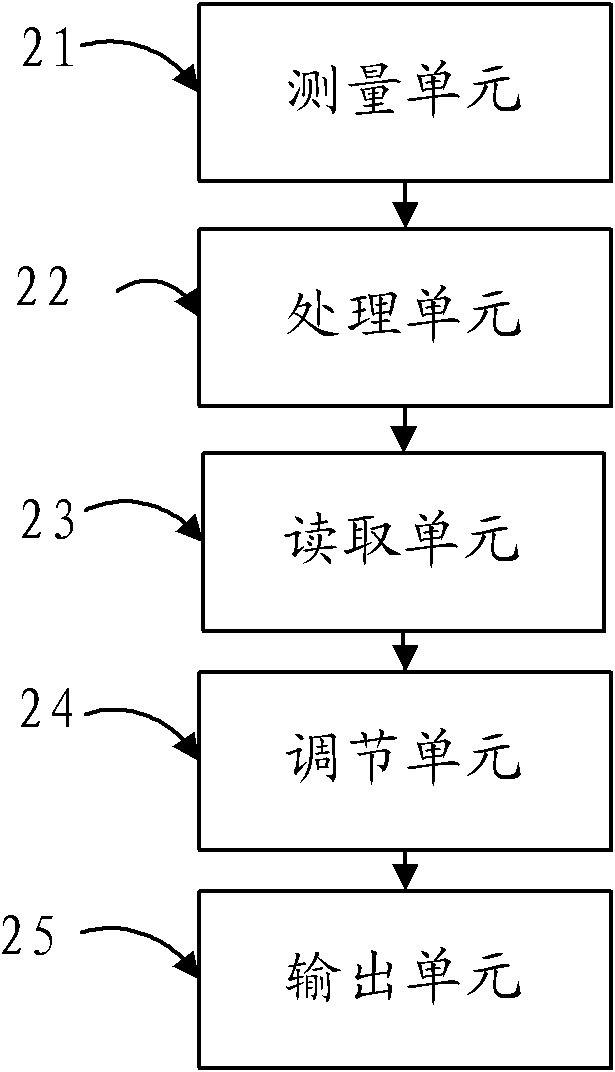
[0064] An embodiment of the present invention provides a flash control device. As shown in the figure, the device includes a configuration unit 41 , a measurement unit 42 , a processing unit 43 , a reading unit 44 , an adjustment unit 45 and an output unit 46 .

[0065] Wherein, the configuration unit 41 is used to configure the lighting condition configuration table, when setting the lighting conditions, read the corresponding lighting conditions from the configured configuration table, and send the lighting conditions to the processing unit 43, measure The unit 42 is used to measure the current ambient illuminance, and sends the measured current ambient illuminance to the processing unit 43, and the processing unit 43 is used to compare the lighting conditions sent by the configuration unit 41 with the current ambient illuminance sent by the measuring unit 43, When the current ambient illuminance is less than the illumination condition, calculate the brightness difference cor...


PUM


Abstract

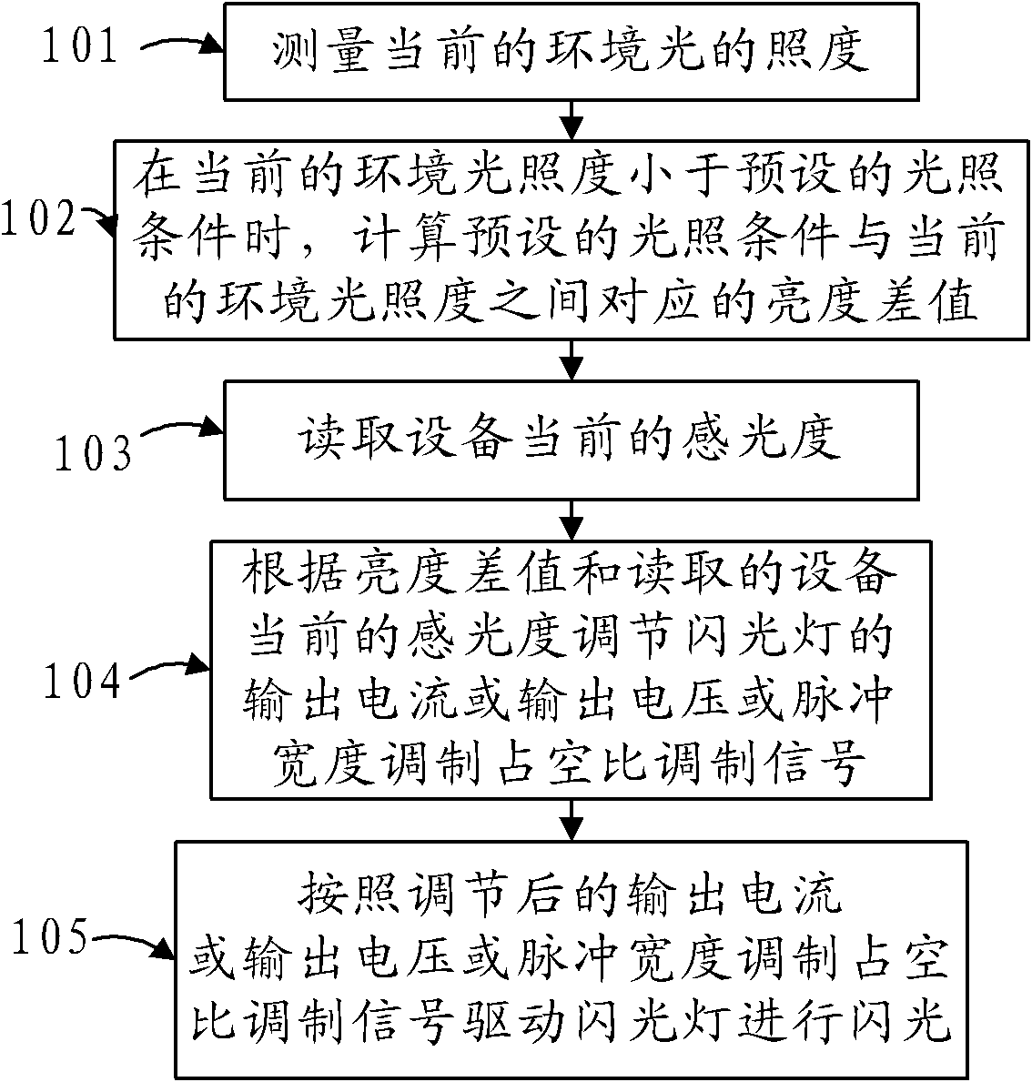
The invention discloses a flash control method and device, relating to the digital technology field and solving the problem that the flash amount of a flashlight can not be regulated according to the practical situation. The flash control method in the embodiment of the invention comprises the following steps: measuring the current ambient light; when the current ambient light is less than the preset lighting condition, calculating a corresponding luminance difference between the preset lighting condition and the current ambient light; reading the current sensitivity of the equipment; according to the luminance difference and the read current sensitivity of the equipment, regulating the output current or the output voltage or pulse width modulation of the current flashlight; and driving the flashlight to flash according to the regulated output current or the output voltage or the pulse width modulation. The embodiment of the invention is mainly used for digital shooting equipment.

Description

technical field [0001] The invention relates to the field of digital technology, in particular to a flash control method and device in the field of digital technology. Background technique [0002] The flash is a supplementary light device, which can ensure clear and bright pictures in dim situations. When shooting outdoors, the flash can also be used as an auxiliary light source to emphasize the tone of the skin. Special effects can also be arranged according to the requirements of the photographer. [0003] Some shooting devices (such as mobile phones with camera functions, thin digital cameras, etc.) are limited by their volume, and their apertures and sensor areas cannot be made large. When taking pictures in low-light environments, there are large noises and unclear images. And other issues. At this time, a flash is needed to assist in reducing this effect. [0004] Generally, there are only three modes for the flash, which are normal open mode, automatic mode and of...

Claims


Application Information

Patent Timeline
Patent Type & Authority Applications(China)
IPC IPC(8): G03B15/05H05B37/02G01J1/16
CPCY02B20/46Y02B20/40
Inventor 钟光华
Owner HUAWEI DEVICE CO LTD
Learn More