Capacitive touch inductor

A touch sensor, capacitive technology, applied in the field of double-sided projected capacitive touch sensors, can solve the problems of reducing the signal strength of the lower layer sensing unit, affecting the visual effect, reducing the sensitivity, etc., to reduce visual defects, improve signal strength, The effect of increasing the capacitance

Inactive Publication Date: 2012-11-28
SOUTHEAST UNIV
View PDF0 Cites 0 Cited by
  • Summary
  • Abstract
  • Description
  • Claims
  • Application Information

AI Technical Summary

Problems solved by technology

Considering that if a protective cover with a certain thickness is added above the sensor, the signal strength of the lower sensing unit will be further reduced, resulting in a decrease in sensitivity
Since the sensing unit of the double-sided capacitive touch screen is located on the upper and lower layers of the substrate, there is a drop, and the sensing unit can be clearly observed from a certain viewing angle, which affects the visual effect

Method used


Image

  • Capacitive touch inductor
  • Capacitive touch inductor
  • Capacitive touch inductor

Examples


Embodiment 1

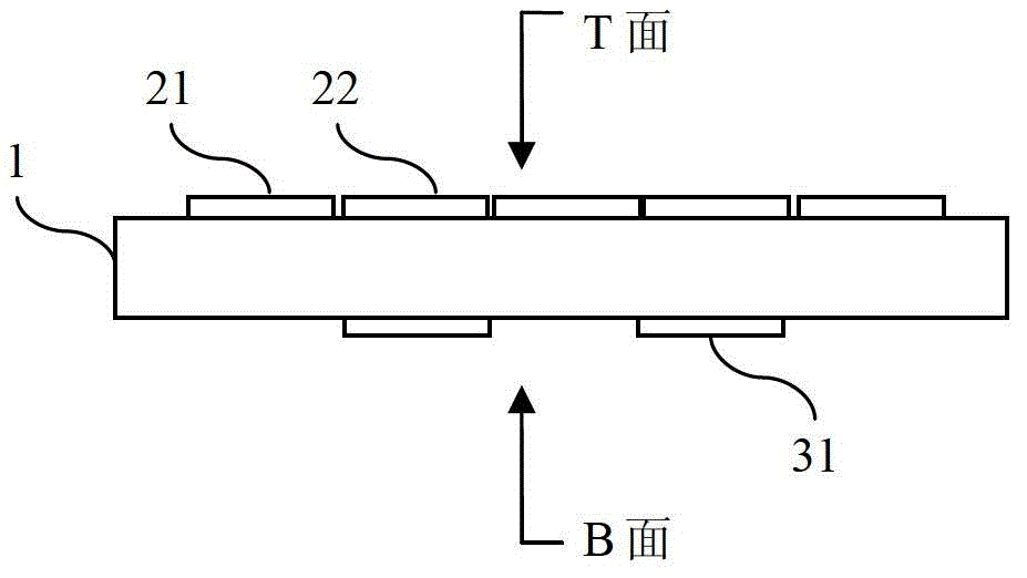
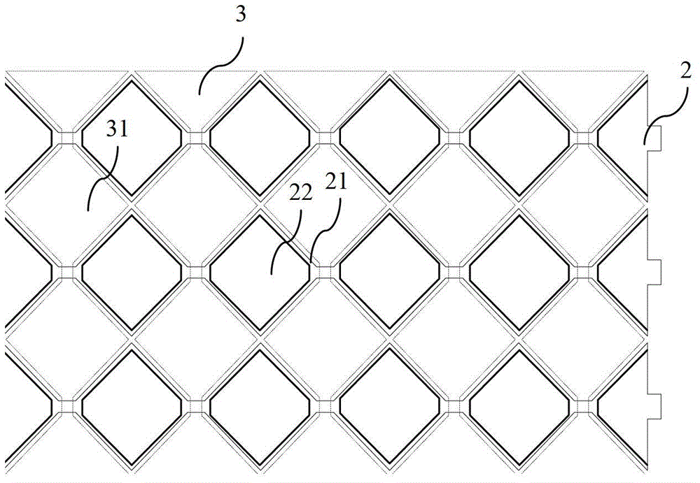
[0029] Such as figure 1 and image 3 The capacitive touch sensor shown includes an insulating substrate 1, a group of first sensing electrodes 2 including an array of first sensing units 21 formed on the upper surface (T surface) of the substrate 1, an array of first auxiliary sensing units 22 and a first 23 groups of induction electrode leads, such as Figure 5 As shown; the second sensing electrode 3 group and the second sensing electrode lead 33 group including the second sensing unit 31 array formed on the lower surface (B surface) of the substrate 1, such as Figure 5 As shown; the first sensing electrode 2 group and the second sensing electrode 3 group are orthogonal to each other; the first sensing unit 21 array and the second sensing unit 31 array are interlaced; the first sensing unit 21 array and the first auxiliary sensing unit 22 The arrays are interlaced and overlapped with the array of the second sensing unit 31; the diagonal length ratio of the first sensing u...

Embodiment 2

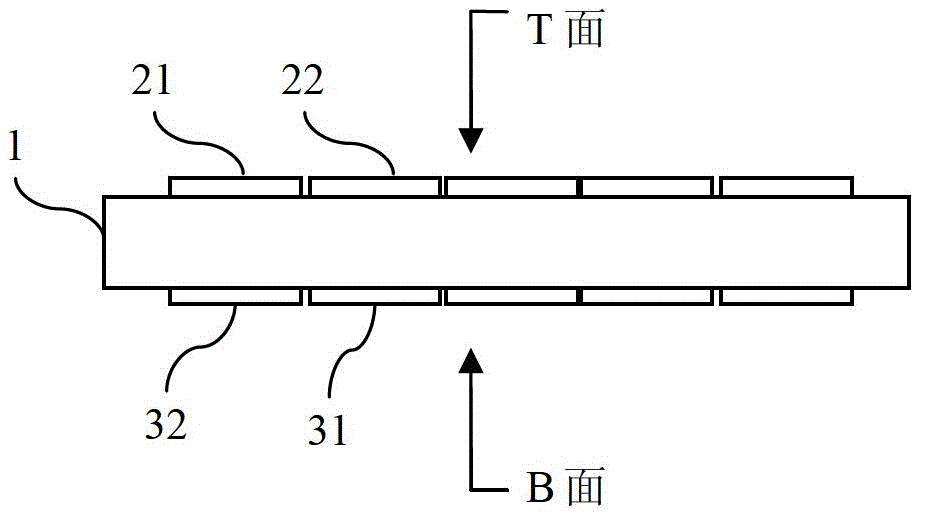
[0031] Such as figure 2 A capacitive touch sensor shown includes an insulating substrate 1, a first sensing electrode 2 group including an array of first sensing units 21 formed on the upper surface (T surface) of the substrate 1, an array of first auxiliary sensing units 22 and a second 23 groups of induction electrode lead wires, such as Figure 5 As shown; the second sensing electrode 3 group including the second sensing unit 31 array, the second auxiliary sensing unit 32 array and the second sensing electrode lead 33 group formed on the lower surface (B surface) of the substrate 1, such as Figure 6 As shown; the first sensing electrode 2 group and the second sensing electrode 3 group are orthogonal to each other; the first sensing unit 21 array and the second sensing unit 31 array are interlaced; the first auxiliary sensing unit 22 and the second auxiliary sensing unit 32 groups are interlaced with each other and overlap with the array of the second sensing unit 31 and ...

Embodiment 3

[0033] In the capacitive touch sensor described in the above-mentioned embodiment 1 or 2, such as Figure 7 As shown, the shapes of the first sensing unit 21 and the second sensing unit 31 are formed by combining and connecting multiple polygons.


PUM

PropertyMeasurementUnit
thicknessaaaaaaaaaa
lengthaaaaaaaaaa

Abstract

The invention provides a capacitive touch inductor comprising an insulating substrate (1), a first induction electrode (2), a first auxiliary induction unit (22) array, a first induction electrode lead (23), a second induction electrode (3) and a second induction electrode lead (33), wherein the first induction electrode (2), the first auxiliary induction unit (22) array and first induction electrode lead (23) are formed on the surface of the insulating substrate (1), and the first induction electrode (2) comprises a first induction unit (21) array; the second induction electrode (3) and thesecond induction electrode lead (33) are positioned on the lower surface of the insulating substrate (1), and the second induction electrode (3) comprises a second induction unit (31) array; the first induction electrode (2) and the second induction electrode (3) are orthogonal to each other; the first induction unit (21) array and the second induction unit (31) array are staggered with each other; and the first induction unit (21) array and the first auxiliary induction unit (22) array are staggered with each other and mutually overlapped with the second induction unit (31) array.

Description

technical field [0001] The invention relates to a capacitive touch sensor, in particular to a double-sided projected capacitive touch sensor. Background technique [0002] For capacitive touch screens, especially double-sided capacitive touch screens, due to the influence of substrate thickness, the amount of electricity absorbed by the finger from the upper and lower layers of sensing capacitors is different, resulting in different detected signal strengths. It is considered that if a protective cover with a certain thickness is added above the sensor, the signal strength of the lower sensing unit will be further reduced, resulting in a decrease in sensitivity. Since the sensing units of the double-sided capacitive touch screen are respectively located on the upper and lower layers of the substrate, there is a drop, and the sensing units can be clearly observed from a certain viewing angle, which affects the visual effect. Contents of the invention [0003] Technical pro...

Claims


Application Information

Patent Timeline
Patent Type & Authority Patents(China)
IPC IPC(8): G06F3/03G06F3/044
Inventor 张雄张浩康樊兆雯王保平
Owner SOUTHEAST UNIV
Why Eureka
Try Eureka