Transformer structure

A transformer and side plate technology, applied in the field of transformers, can solve problems such as difficult storage and exposure, dangerous use, damage to extension cords, etc., to improve convenience and competitiveness, and solve the effects of difficult storage

Inactive Publication Date: 2011-06-01
INVENTEC CORP
View PDF0 Cites 2 Cited by
  • Summary
  • Abstract
  • Description
  • Claims
  • Application Information

AI Technical Summary

Problems solved by technology

[0005] The extension wire attached to the existing transformer has problems such as difficult storage and exposure, a

Method used


Image

  • Transformer structure
  • Transformer structure
  • Transformer structure

Examples


Embodiment Construction

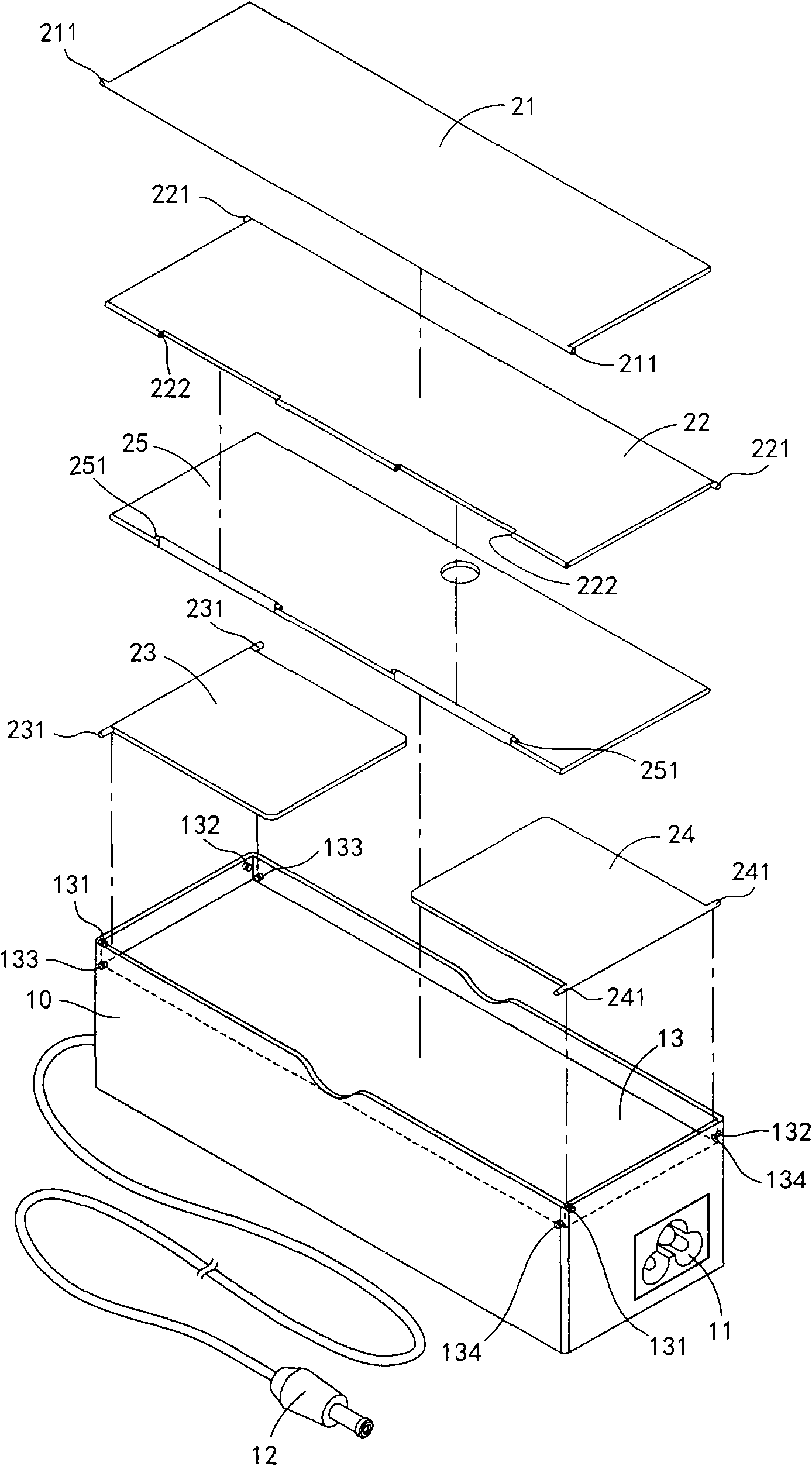
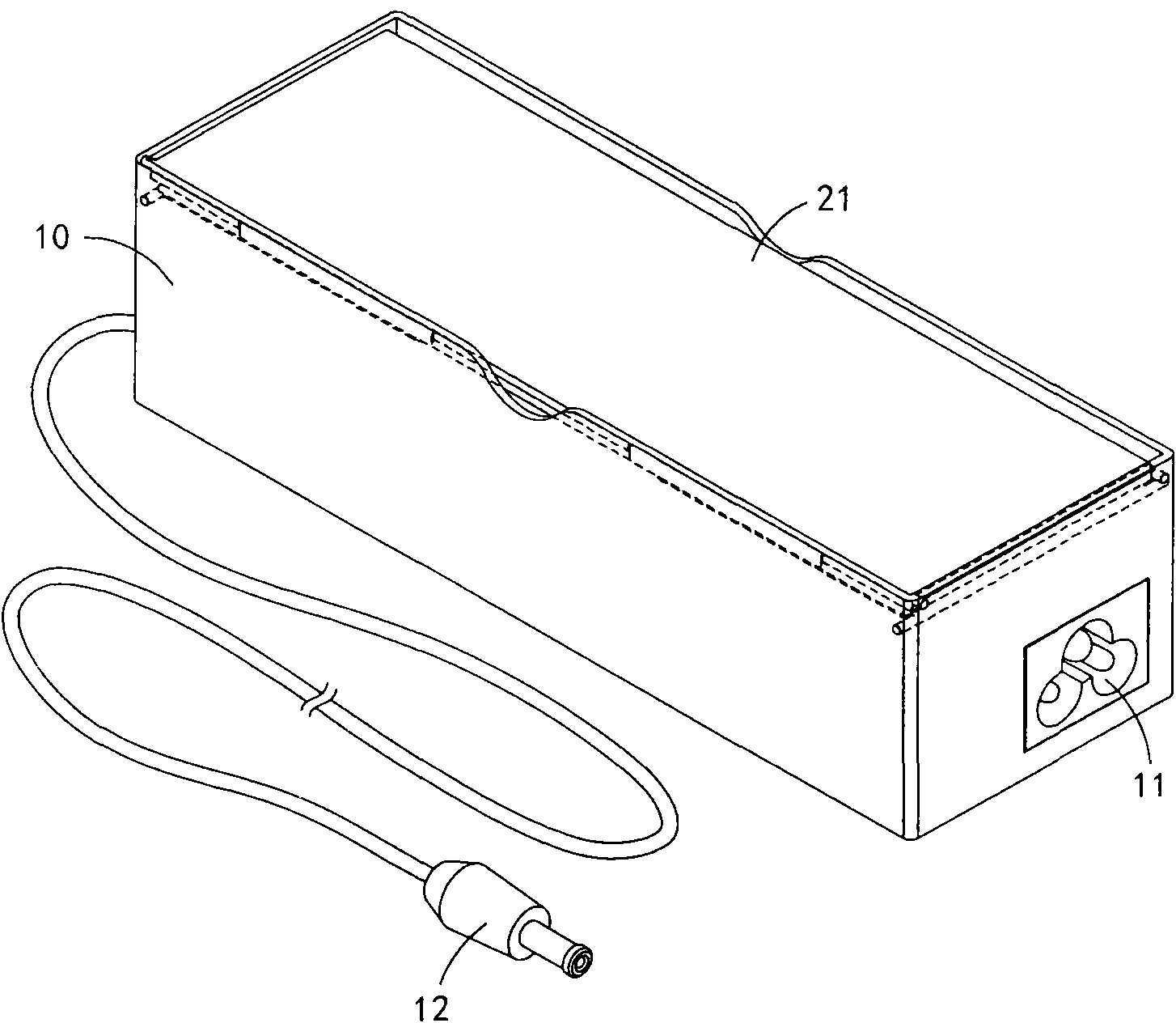
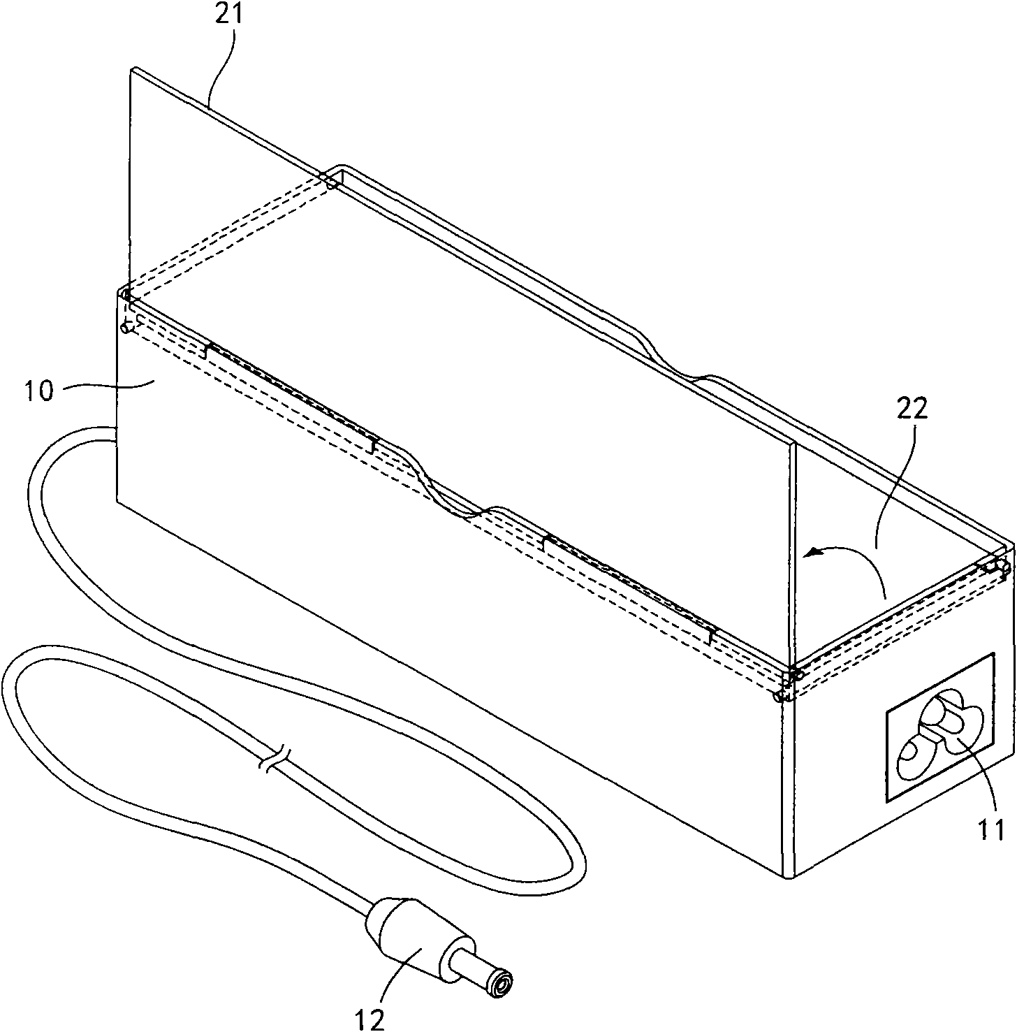
[0062] Below in conjunction with accompanying drawing, structural principle and working principle of the present invention are specifically described:

[0063] see Figures 1 to 2E The schematic diagram shown, where, figure 1 It is an exploded schematic diagram of a transformer structure according to an embodiment of the present invention. Figure 2A It is a schematic diagram of the appearance of each side plate of the transformer structure when folded according to an embodiment of the present invention. Figure 2B It is a schematic diagram of the appearance of the transformer structure according to an embodiment of the present invention when the first side plate is reversed and erected. Figure 2C It is a schematic view of the appearance of the transformer structure erected on the reversed second side plate according to an embodiment of the present invention. Figure 2D It is a schematic view of the appearance of the transformer structure according to an embodiment of the ...


PUM


Abstract

The invention relates to a transformer structure. A voltage transformation circuit is contained in a shell, multiple side plates are movably arranged on the shell, and the multiple side plates are moved to an unfolding position relative to the shell, thus the multiple side plates are adjacent and form a containing space by surrounding. Thus an accessory such as a wire rod can be easily contained in the containing space, the problem that an extension line is difficult to contain is solved, and the convenience and competitiveness of the product are improved.

Description

technical field [0001] The invention relates to a transformer, in particular to a transformer structure for expanding storage space. Background technique [0002] A general transformer can properly step up and step down an alternating current to convert it into direct current and is widely used in various electronic consumer products, such as battery chargers, modems, notebook computers and other electronic appliances that require specific voltages. Therefore, when various electronic appliances are sold, the transformer required by the product will be attached to provide the DC voltage required by the electronic and electrical product. [0003] However, the specifications and sizes of transformers provided by various electronic appliances are different. Therefore, when these transformers are used, various extension cords of different lengths are usually configured, and the extension cords are electrically connected to an AC power outlet. However, when the transformer is no...

Claims


Application Information

Patent Timeline
IPC IPC(8): H02M1/00H02M7/02H05K5/00
Inventor 赖昌卿许亚焄
Owner INVENTEC CORP
Why Eureka
Try Eureka