Method for realizing linear phase IIR (infinite impulse response) filter

An IIR filter, linear phase technology, applied in the field of signal processing, can solve the problems of no amplitude-frequency characteristics, large delay, filter instability, etc., achieve good amplitude-frequency characteristics and linear phase characteristics, and reduce waveform distortion errors. , to ensure the effect of real-time requirements

Active Publication Date: 2011-06-01
GUANGDONG BIOLIGHT MEDITECH CO LTD
View PDF4 Cites 3 Cited by
  • Summary
  • Abstract
  • Description
  • Claims
  • Application Information

AI Technical Summary

Problems solved by technology

Usually the FIR filter is easy to satisfy the linear phase characteristic, but its calculation amount is quite large; the narrow-band power frequency notch filter designed by the simple integer coefficient method can also satisfy the linear phase characteristic, but it has a large delay, And it will require the sampling rate to be an integer multiple of the notch point, which is also a constraint on the design of different frequency band notch filters; while the IIR notch filter designed by conventional methods cannot have more accurate linear phase characteristics, because its zero and pole No mirror symmetry, if the pole is required to be mirror symmetric about the zero point, the pole will be outside the unit circle, causing the filter to be unstable
[0003] Later, there were improvements in the method, for example, the phase equalization of IIR filtering was realized through the all-pass filter, but its calculation amount was sometimes increased compared with the traditional FIR filter; the design of IIR through equal ripple and maximum flat group delay method filter, but it does not have ideal amplitude-frequency characteristics; there is also a traditional zero-phase IIR filter with more reports, which is composed of timing inversion and multi-channel filtering. Through recursive calculation, the amplitude-frequency characteristics and linearity are maintained. Phase, but it is mainly for finite length sequence inversion, and reverse IIR filtering cannot be realized in real time, which limits its application in occasions with high real-time requirements such as continuous signals

Method used


Image

  • Method for realizing linear phase IIR (infinite impulse response) filter
  • Method for realizing linear phase IIR (infinite impulse response) filter
  • Method for realizing linear phase IIR (infinite impulse response) filter

Examples


Embodiment Construction

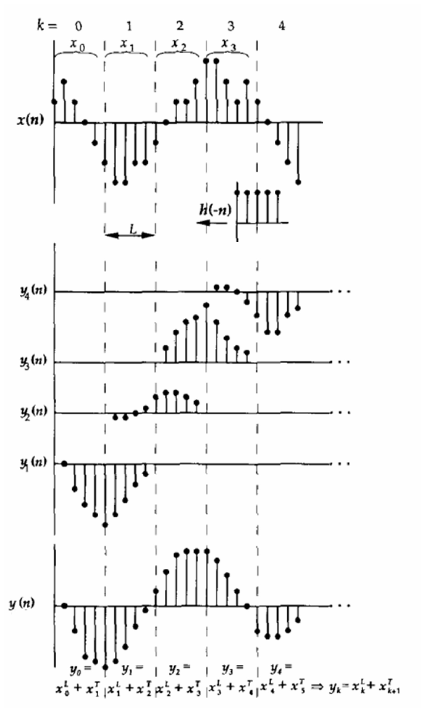
[0027] The implementation method of the linear phase IIR filter of the present invention includes the steps of dividing equal-length segments for time sequence inversion, zero input extension and then performing reverse filtering, re-time sequence inversion, and forward filtering. They are described in detail below.

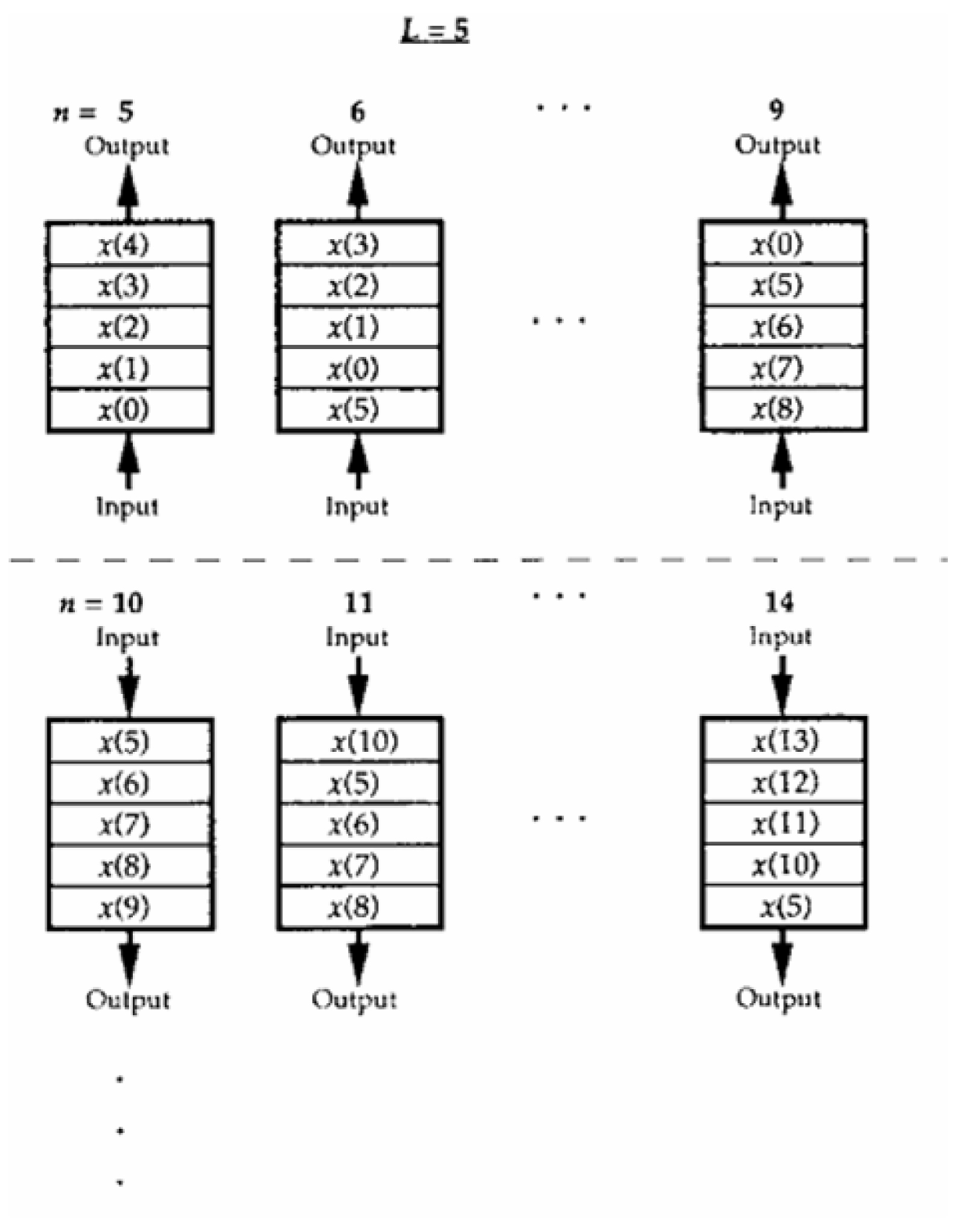
[0028] Step (1): Divide segments of equal length for timing inversion. After sampling the infinitely long continuous signal, x(n)={x(0),x(1),x(2),…} is obtained, divided into equal-length segments of length L according to the time sequence, and the equal-length segments are sequentially Timing reversed. The timing reversal method generally adopts the following steps:

[0029] a. A register with a length of L is preset, and the two ends of the register are respectively the first input and output terminals and the second input and output terminals; b. L signals x(0),..., of the first segment of x(n) x(L) is sequentially stored in the register from the first inpu...


PUM


Abstract

The invention discloses a method for realizing a linear phase IIR (infinite impulse response) filter, and the method comprises the following steps: dividing isometric segments and performing time reversal; inversely filtering after prolonging zero input; and performing time reversal again and carrying out forward filtering and the like. By utilizing the method, an infinite continuous signal application in a real-time occasion can be met, the linear phase is realized while the calculation quantity is greatly reduced, the waveform distortion error is reduced, and a good amplitude-frequency characteristic is ensured.

Description

technical field [0001] The invention belongs to the field of signal processing, in particular to a method for realizing a linear phase IIR filter. Background technique [0002] In order to avoid various interferences from affecting the signal acquisition and recording process, it is generally necessary to set a filter to filter out these interferences. In the actual filtering process, it is often desired not to change the waveform or reduce waveform distortion, so if the designed filter has a linear phase response, this will be their ideal characteristic, which will cause little waveform distortion. The same is true in the design process of the notch filter. Usually the FIR filter is easy to satisfy the linear phase characteristic, but its calculation amount is quite large; the narrow-band power frequency notch filter designed by the simple integer coefficient method can also satisfy the linear phase characteristic, but it has a large delay, And it will require the sampli...

Claims


Application Information

Patent Timeline
IPC IPC(8): H03H17/02
Inventor 刘伟
Owner GUANGDONG BIOLIGHT MEDITECH CO LTD
Why Eureka
Try Eureka