Plane coil

A planar coil, coil technology, applied in the direction of transformer/inductor coil/winding/connection, preventing/reducing unwanted electrical/magnetic influence, transformer, etc., can solve problems such as hindering thinning and large outer diameter of stranded wire

Inactive Publication Date: 2011-06-01
PANASONIC CORP
View PDF1 Cites 47 Cited by
  • Summary
  • Abstract
  • Description
  • Claims
  • Application Information

AI Technical Summary

Problems solved by technology

[0005] However, if the litz wire 83 is used in the planar coil 82, since the litz wire is formed by twisting a plurality of conducting wires, the outer diameter of the twisted wire is large, which hinders thinning.

Method used


Image

  • Plane coil
  • Plane coil
  • Plane coil

Examples


Embodiment Construction

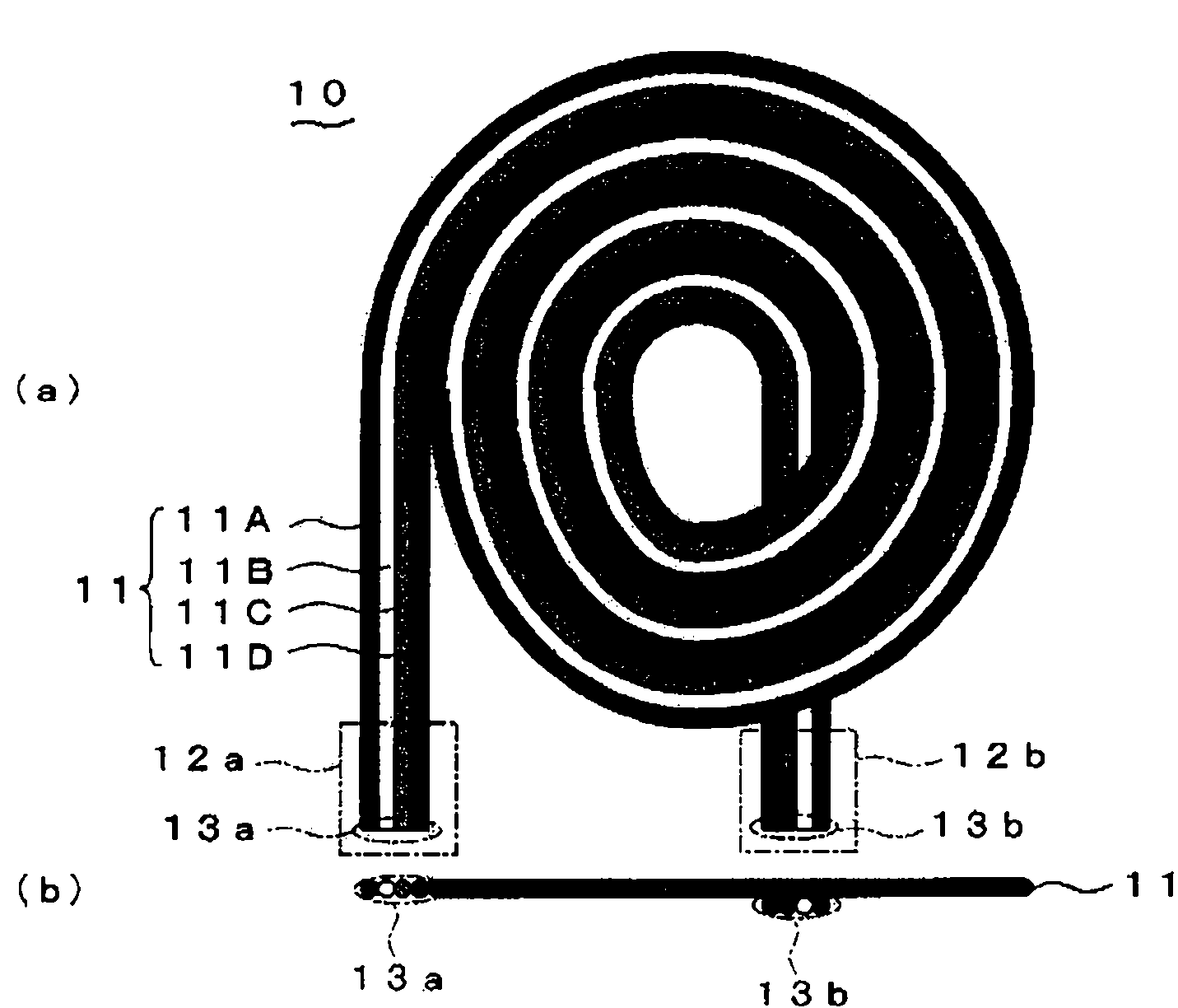
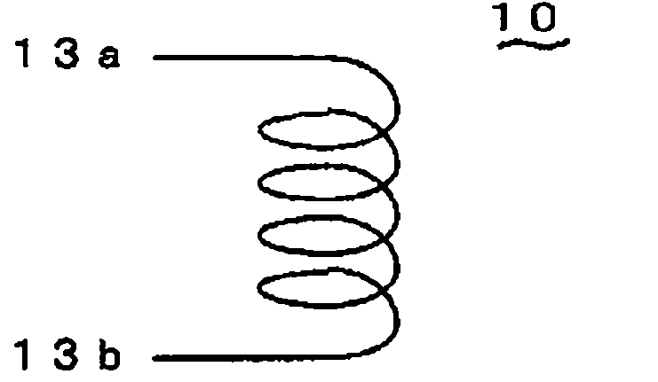
[0052] figure 1 (a) and figure 1(b) shows the structure of the planar coil 10 which concerns on 1st Embodiment which actualized this invention. This planar coil 10 is formed by arranging a plurality of conductive wires 11A, 11B, 11C, and 11D (hereinafter collectively referred to as conductive wires 11 ) parallel to each other in a substantially planar shape and wound in a spiral shape. Ends 13 a , 13 b of conductive wire 11 are located on coil lead-outs 12 a , 12 b of planar coil 10 . The ends 13a of the parallel conductive wires 11 are electrically connected at the coil lead-out part 12a, and the respective ends 13b of the other ends are electrically connected at the other coil lead-out part 12b, so that the conductive wires 11 are connected in parallel. The conductive wires 11 are insulated from each other between the end portion 13a and the end portion 13b. The number of conductive wires 11 is not limited to four, but can be more than two, and the diameter and length c...


PUM


Abstract

Disclosed is a plane coil which is made thin while an increase in effective resistance in the high frequency region is minimized. A plane coil (10) is configured such that a plurality of electrically conductive wires (11) arranged in parallel with each other are wound spirally while being arranged planarly, and are connected in parallel because the ends (13a) of the respective electrically conductive wires (11) are connected electrically with each other at a coil lead-out portion (12a) and the ends (13b) thereof are also connected with each other at a coil lead-out portion (12b). Since the electrically conductive wires (11) of the plane coil (10) are arranged substantially planarly, coil thickness does not increase and the plane coil (10) is made thin. Furthermore, an increase in effective resistance due to skin effect is minimized in the high frequency region because the plurality of electrically conductive wires (11) are connected in parallel.

Description

technical field [0001] The present invention relates to planar coils used in non-contact power transmission devices and the like. Background technique [0002] Conventionally, as a non-contact power transmission technology, a non-contact power transmission device using electromagnetic induction of a coil has been proposed, for example, as described in Japanese Patent Laid-Open No. 2006-42519. Figure 15 Indicates such a device. The non-contact power transmission device 80 has a power transmission side coil 81S and a power reception side coil 81R (hereinafter, collectively referred to as coils 81 ) that face each other. Electric power is transmitted to the power receiving side coil 81R by passing an alternating current through the power transmitting side coil 81S and by electromagnetic induction. Figure 16 (a) and (b) show the shape of the planar coil used for the coil 81 . The coil of the planar coil 82 is configured in a spiral planar shape and is thinned. [0003] In o...

Claims


Application Information

Patent Timeline
Patent Type & Authority Applications(China)
IPC IPC(8): H01F17/00H01F27/28H01F38/14H02J17/00
CPCH01F2027/348H01F27/34H01F38/14H01F27/2871H01F27/2823
Inventor 田村秀树太田智浩加田恭平铃木诚之
Owner PANASONIC CORP
Why Eureka
Try Eureka