
Reconfigurable base station antenna

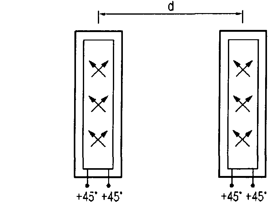
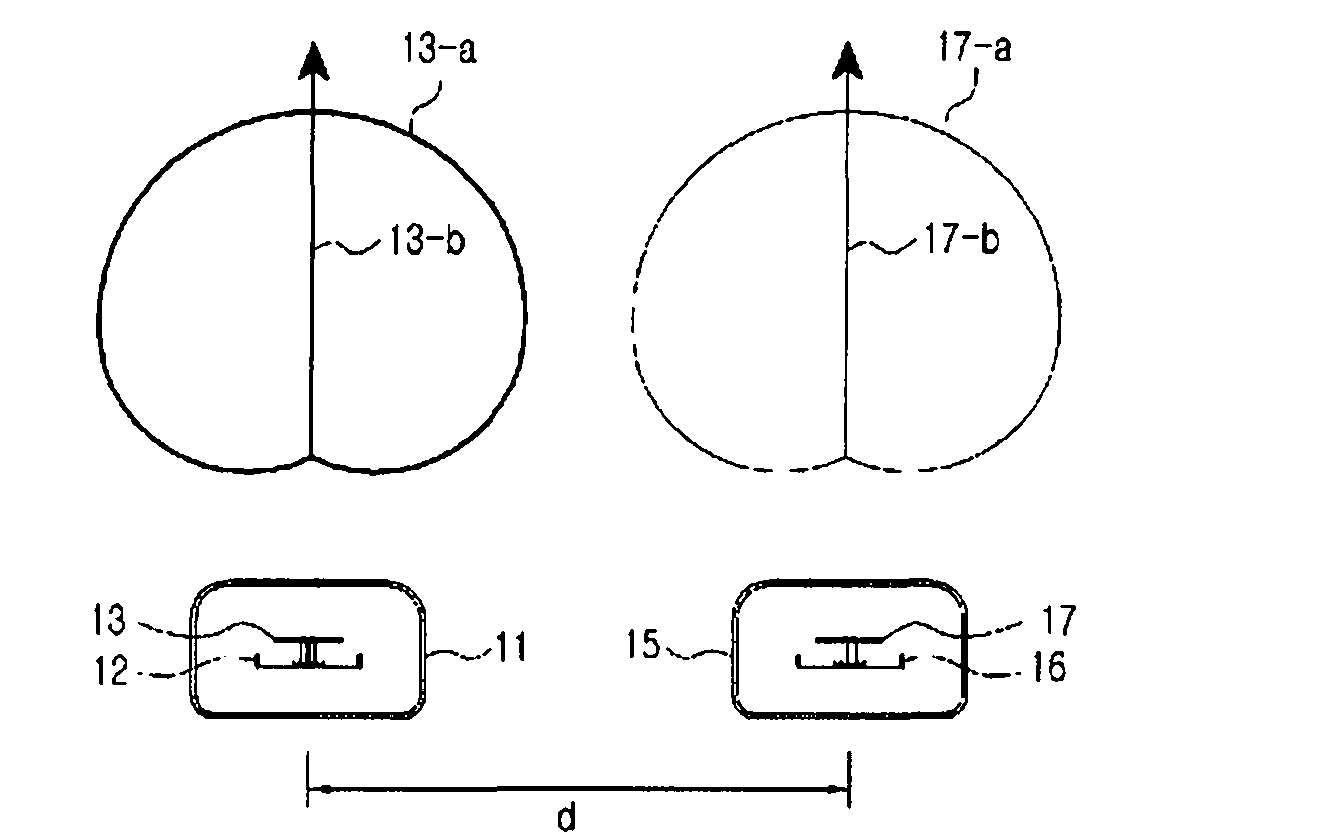
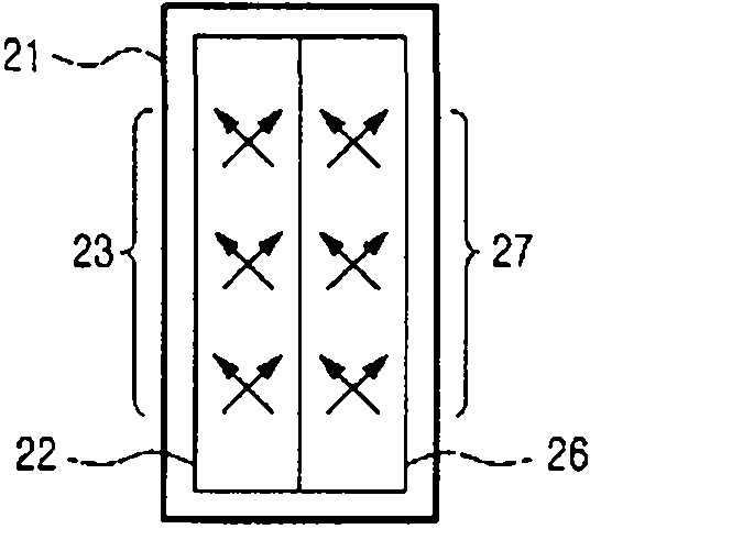
An antenna and base station technology, applied in the field of BS antennas, can solve the problems of consuming a lot of time, energy and cost, difficulty in coping with changes in the wave propagation environment and subscriber distribution time, and achieve the effect of increasing the capacity of the cell

Inactive Publication Date: 2011-06-01
KMW INC
View PDF6 Cites 17 Cited by
  • Summary
  • Abstract
  • Description
  • Claims
  • Application Information

AI Technical Summary

Problems solved by technology

Although the antenna itself or the antenna configuration can be changed on the tower when required, this effort takes a lot of time, effort and cost to change and optimize the antenna for a specific environment that is not static
In addition, it is difficult to cope with changes in the wave propagation environment and subscriber distribution over time
That is, conventional techniques have limitations such as load balancing and reflecting the communication environment in real time, and there is no specialized technique for steering antenna beams to hotspots

Method used


Image

  • Reconfigurable base station antenna
  • Reconfigurable base station antenna
  • Reconfigurable base station antenna

Examples


Embodiment Construction

[0027] The content defined in the following exemplary description, such as detailed construction and elements, is provided for illustrative purposes, so as to facilitate a comprehensive understanding of exemplary embodiments of reconfigurable base station antennas according to the present invention, but does not The invention is limited to the exemplary embodiments shown and described. Accordingly, those of ordinary skill in the art will recognize that various modifications and variations can be made to the exemplary embodiments described herein without departing from the spirit of the invention and the scope of the appended claims. Also, descriptions of well-known functions and constructions may be omitted for clarity and conciseness.

[0028] While providing mobile communication services on the existing communication service network (such as 2G or 3G network), a lot of funds are invested in building a new communication service network (such as 4G network). Transitioning bet...


PUM


Abstract

A reconfigurable base station (BS) antenna permits increasing cell capacity by dynamically varying an antenna's configuration according to a wave propagation environment and subscriber distribution. At least two reflective plates each have at least one radiator, a ray dome accommodates the two reflective plates in a hollow interior, and upper and lower caps are combined with upper and lower portions of the ray dome, respectively. Reflective connection members are connected to the respective two reflective plates and the upper and lower caps, so that the two reflective plates are rotatable, and at least one force generator provides a rotation force, and at least one force transfer mechanical portion transfers the rotation force received from the force generator to at least one reflective plate and controls a rotation angle of the at least one reflective plate. At least one of the force generator and the force transfer mechanical portion is combined with the two reflective plates.

Description

technical field [0001] The present invention generally relates to a base station (BS) antenna. More particularly, the present invention relates to a BS antenna supporting a multi-antenna scheme and increased transmission capacity in wireless communication. Background technique [0002] With the development of mobile communication technology, the emergence of fourth generation (4G) networks is expected to start operating long before third generation (3G) networks become saturated. The main international standard for 4G networks, Mobile WiMAX or Long Term Evolution (LTE), is trying to maximize the data rate per frequency band, ie increase capacity (bps / Hz) based on multiple antenna technology. Of these, a multiple-antenna technique known as multiple-input multiple-output (MIMO) is currently most effectively used to increase capacity. [0003] For BS antennas, although the multi-antenna technique is based on baseband signal processing, the capacity increase achieved with mult...

Claims


Application Information

Patent Timeline
Patent Type & Authority Applications(China)
IPC IPC(8): H01Q19/10H01Q21/10
CPCH01Q1/246H01Q9/12H01Q3/06H01Q1/084H01Q21/10
Inventor 文营灿邵盛焕金仁昊
Owner KMW INC
Learn More