Leveling control method of finishing mill

A control method and finishing mill technology, applied in the direction of contour control, etc., can solve the problems of high labor intensity and low leveling accuracy of operators, and achieve the effect of reducing labor intensity and improving leveling accuracy

Inactive Publication Date: 2011-06-08
TANGSHAN GUOFENG IRON & STEEL
View PDF0 Cites 13 Cited by
  • Summary
  • Abstract
  • Description
  • Claims
  • Application Information

AI Technical Summary

Problems solved by technology

[0003] In the prior art, in order to eliminate the wave type, the operator judges the wave type according to the actual observation on site, and determines the leveling value based on experience, so as to manually level the finishing mill. The principle of the leveling control is: when When the wave is on the transmission side, pres

Method used


Image

  • Leveling control method of finishing mill
  • Leveling control method of finishing mill
  • Leveling control method of finishing mill

Examples


Embodiment Construction

[0019] In order to make the object, technical solution and advantages of the present invention clearer, the solutions of the present invention will be further described in detail below with reference to the accompanying drawings and examples.

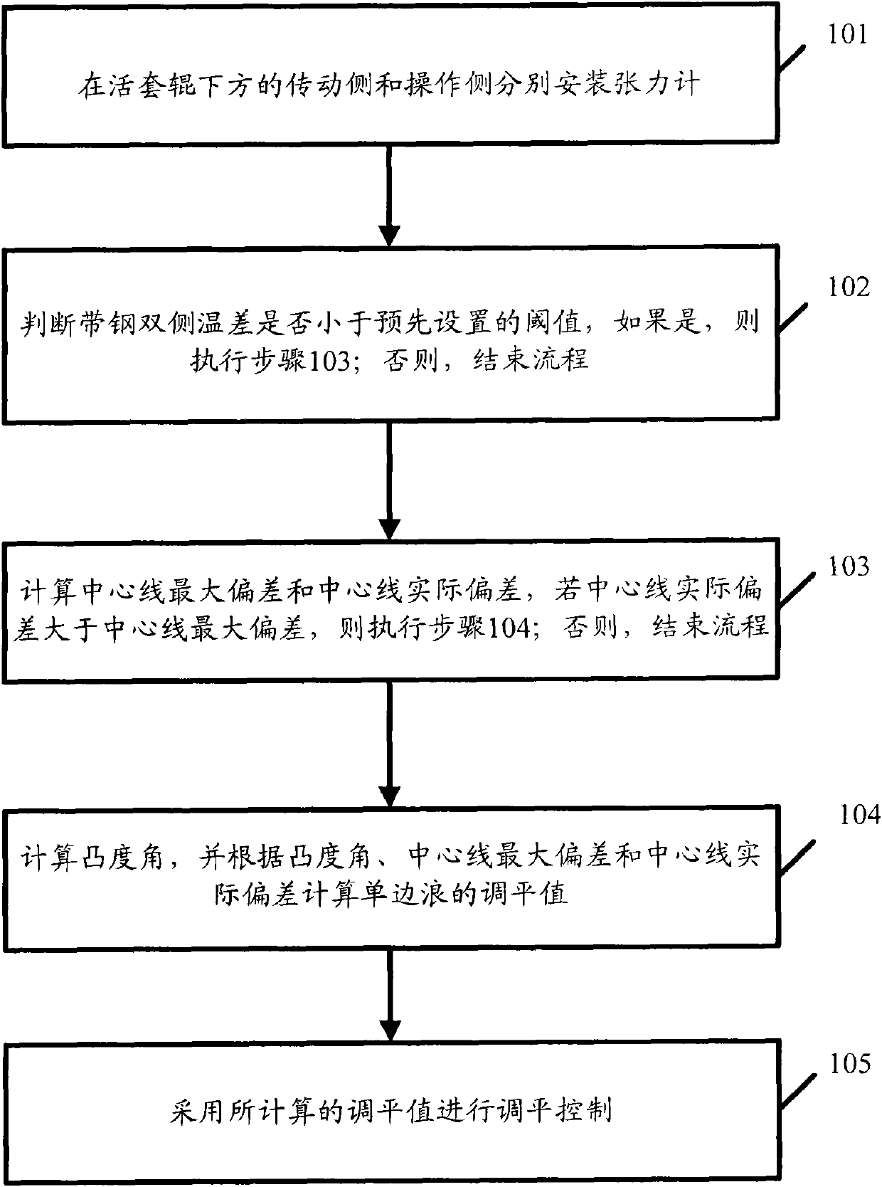
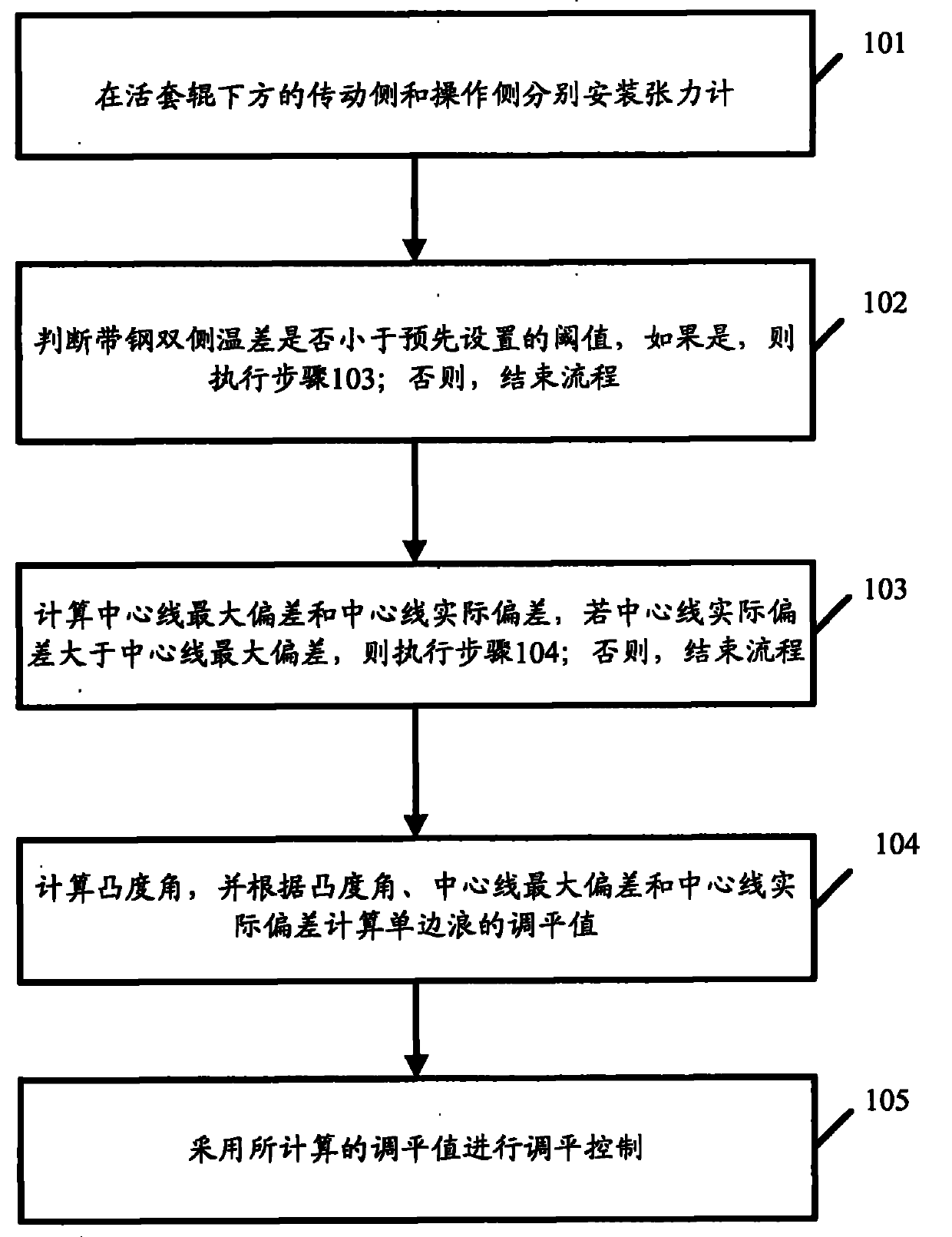
[0020] figure 1 It is a flow chart of an embodiment of a leveling control method of a finishing mill provided by the present invention. Such as figure 1 As shown, the method includes the following steps:

[0021] In step 101, tension gauges are respectively installed on the driving side and the operating side below the looper roller.

[0022] In practical applications, in order to ensure that the second flow rate of the strip between two adjacent finishing mills is equal and the tension of the strip between the racks is constant, a looper device is also installed between the two adjacent finishing mills, wherein the looper The device includes a looper roller, which is located in the direction perpendicular to the transmission directi...


PUM


Abstract

The invention discloses a leveling control method of a finishing mill. The transmission side and the operation side below a looper roll are respectively provided with a tension meter in advance, and the tension meters are used for respectively measuring tensions of strip steel at the transmission side and the operation side. When leveling control needs to be carried out, the method comprises the steps of: A, calculating a center line maximum deviation and a center line actual deviation, if the center line actual deviation is more than the center line maximum deviation, executing the step B, and if not, ending the process; B, calculating the convexity angle of the strip steel in the current position, calculating the leveling value of a unilateral wave according to the convexity angle, the center line maximum deviation and the center line actual deviation; and C, carrying out leveling control by adopting the leveling value of the unilateral wave. By adopting the method, the labor intensity of operators can be reduced and the leveling precision is improved.

Description

technical field [0001] The invention relates to hot rolling technology, in particular to a leveling control method of a finish rolling mill. Background technique [0002] In the hot rolling process, the finishing mill is used to determine the specific thickness, width and shape of the strip. Ideally, the thickness of the strip should be equal at each position at the same distance from the slab centerline of the strip. That is to say, the thickness of the strip steel is distributed symmetrically with respect to the slab centerline of the strip steel, but, due to various reasons, in practical applications, the thickness of the strip steel may not be symmetrically distributed with respect to the slab centerline , a wave pattern appears. In practical applications, with the slab centerline as the center of symmetry, one side of the strip is called the operating side, and the other side is called the transmission side, and the side closest to the operator is usually called the op...

Claims


Application Information

Patent Timeline
IPC IPC(8): B21B37/28
Inventor 王林孙善林梁井义晏宗刚
Owner TANGSHAN GUOFENG IRON & STEEL
Why Eureka
Try Eureka