Clamp for automatic quick replacing

An automatic and fast technology, applied in the field of manipulators, can solve problems that affect production efficiency, tediousness, waste of manpower and time, etc., and achieve the effects of increased production efficiency, small size, and reduced labor intensity

Inactive Publication Date: 2011-06-08
NINGBO WELLLIH ROBOTS TECH CO LTD
View PDF0 Cites 9 Cited by
  • Summary
  • Abstract
  • Description
  • Claims
  • Application Information

AI Technical Summary

Problems solved by technology

Existing defects: when the manipulator takes another product with different dimensions or weight, another fixture needs to be replaced
At this time, the process of replacing the jig is cumbersome. It is necessary to remove the screw to remove the original jig of the manipulator, and then fasten the jig to be replaced on the side of the manipulator with screws, which wastes manpower and time, and affects production. efficiency

Method used


Image

  • Clamp for automatic quick replacing
  • Clamp for automatic quick replacing
  • Clamp for automatic quick replacing

Examples


Embodiment

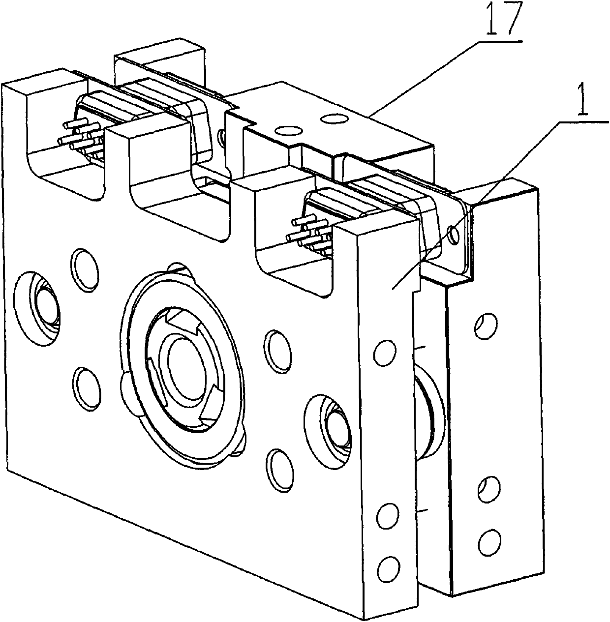
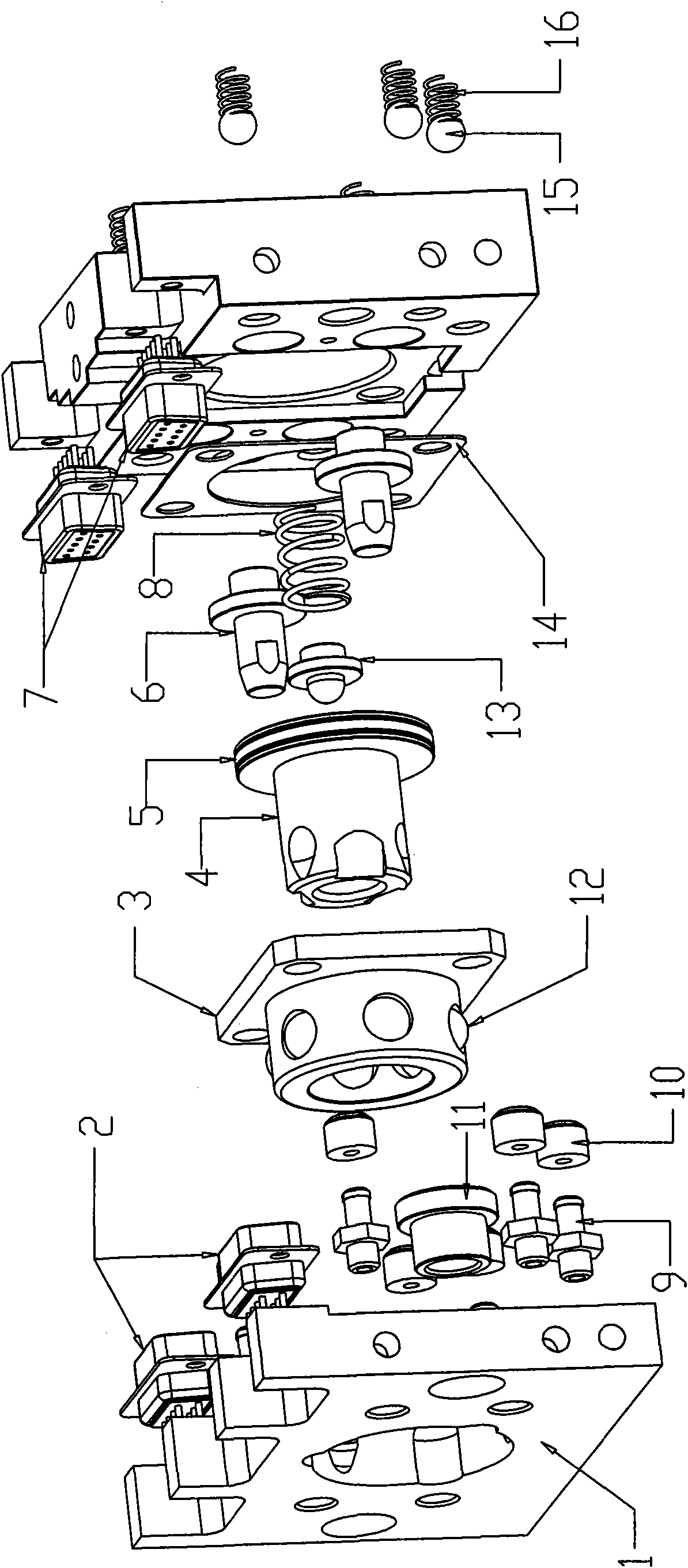
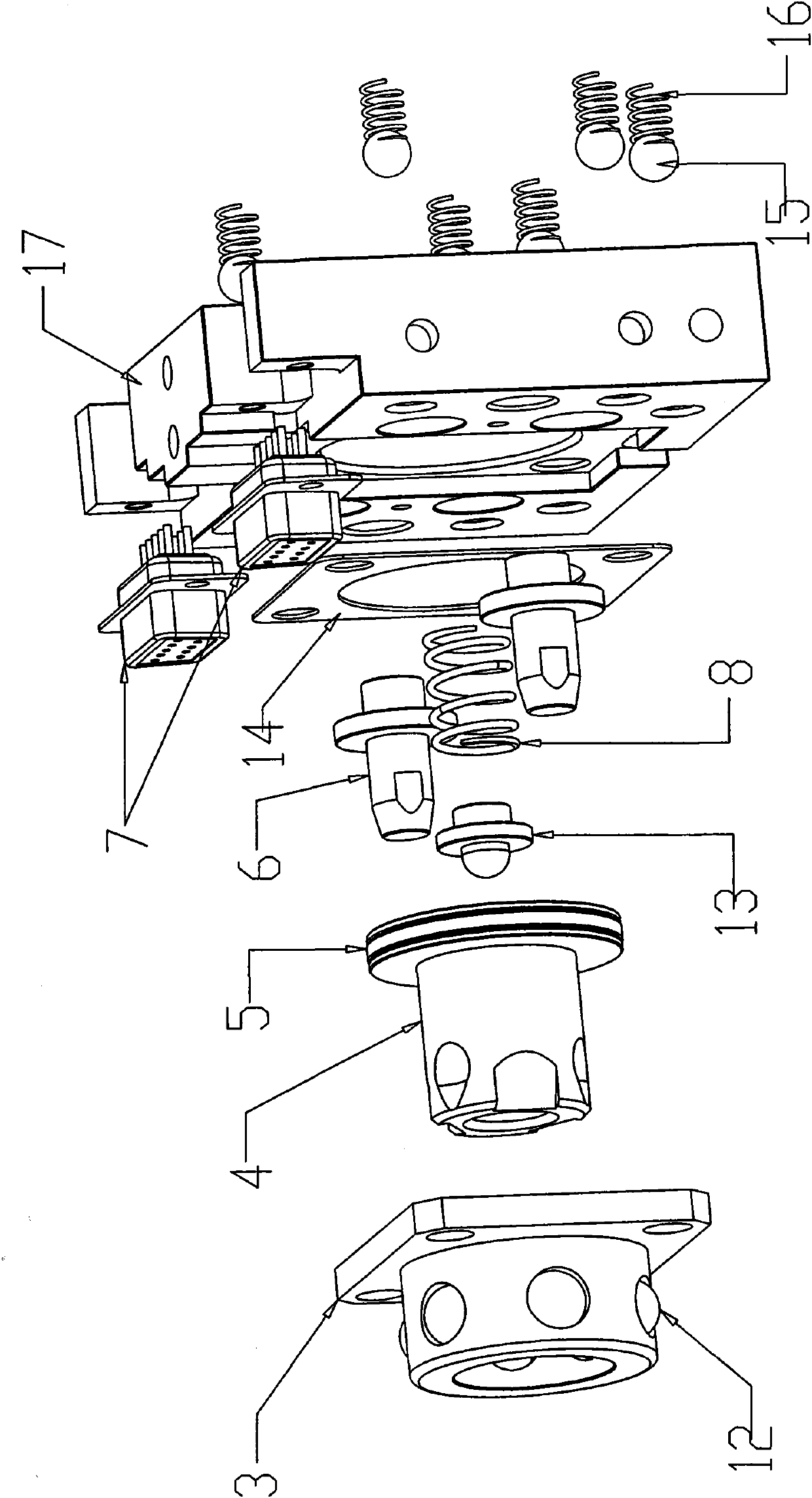
[0030] Such as figure 1 , figure 2 , image 3 , Figure 4 The automatic quick-change jig is divided into two parts, the A-part device and the B-part device. Among them, the device of part A is installed on the side posture of the manipulator. The structure of the A part device is: the arm side mounting plate 17 is used as the base body of the A part, and the plate body is processed with a plurality of ventilation holes and threaded connection holes. The spring A8 is placed in the center of the circular groove of the mounting plate 17 on the arm side, and the spring positioning head 13 is placed on the upper end of the spring A8. The hole at the piston end of the central axis 4 is aligned with the spring positioning head 13 and pressed down. The sealing ring 5 is installed, and the piston end is set in the circular groove of the arm side mounting plate 1; there are six steel ball placement holes for the shaft sleeve 3, and six steel balls A12 of corresponding specification...


PUM


Abstract

The invention discloses a clamp for automatic quick replacing, which is characterized in that: the clamp is provided with an A part device arranged on the side gesture of a mechanical arm and a B part device arranged on a jig, wherein the A part device is matched and connected with the B part device; the A part device is provided with an arm side installation plate; a plurality of air vents, check valves and threaded connection holes are formed on a plate body; a circular groove is formed in the middle of the plate body; a central shaft with a piston is arranged in the circular groove; an outer ring of the central shaft piston is in sealing fit with the inner diameter of the circular groove; a matching shaft sleeve is sleeved outside the piston of the central shaft; the B part device is provided with a jig side installation plate; and the middle of the jig side installation plate is provided with a central circular hole matched with a shaft head of the matching shaft sleeve on the arm side installation plate, a plug or a socket matched with the socket or the plug, the air vents matched with the check valves and ventilating joints connected to the air vents. The clamp for automatic quick replacing can quickly replace the jig and is small in volume and advanced in functions.

Description

technical field [0001] The invention relates to a manipulator, in particular to a clamp for quick exchange. Background technique [0002] At present, the special manipulators in the injection molding machine industry are usually connected to the product removal jigs by connecting the jigs with screws and installing them on the side of the manipulator. Existing defects: When the manipulator takes another product with different dimensions or weight, another fixture needs to be replaced. At this time, the process of replacing the jig is cumbersome. It is necessary to remove the screw to remove the original jig of the manipulator, and then fasten the jig to be replaced on the side of the manipulator with screws, which wastes manpower and time, and affects production. efficiency. Contents of the invention [0003] The present invention mainly solves the shortcomings of the prior art and aims at the above-mentioned practical problems, and develops an automatic quick-change jig...

Claims


Application Information

Patent Timeline
Patent Type & Authority Applications(China)
IPC IPC(8): B25J19/00
Inventor 裘洪立
Owner NINGBO WELLLIH ROBOTS TECH CO LTD
Why Eureka
Try Eureka