Check patentability & draft patents in minutes with Patsnap Eureka AI!

Piston pump and hydraulic device of vehicle brake system, and vehicle brake system

A technology of vehicle brakes and hydraulic devices, which is applied to components, brakes, pumps, etc. of pumping devices for elastic fluids, and can solve problems such as piston pump function damage, heat load applied to seals, seal damage, etc., to achieve Anti-wear phenomenon, long service life effect

Inactive Publication Date: 2011-06-08
ROBERT BOSCH GMBH
View PDF5 Cites 9 Cited by
  • Summary
  • Abstract
  • Description
  • Claims
  • Application Information

AI Technical Summary

Problems solved by technology

This leakage impairs the function of the piston pump in an undesirable manner
[0005] The piston can also heat up due to friction on the eccentric bearing, especially on the drive side, which can then exert a thermal load on the seal, which can be damaged

Method used


Image

  • Piston pump and hydraulic device of vehicle brake system, and vehicle brake system
  • Piston pump and hydraulic device of vehicle brake system, and vehicle brake system

Examples


Embodiment Construction

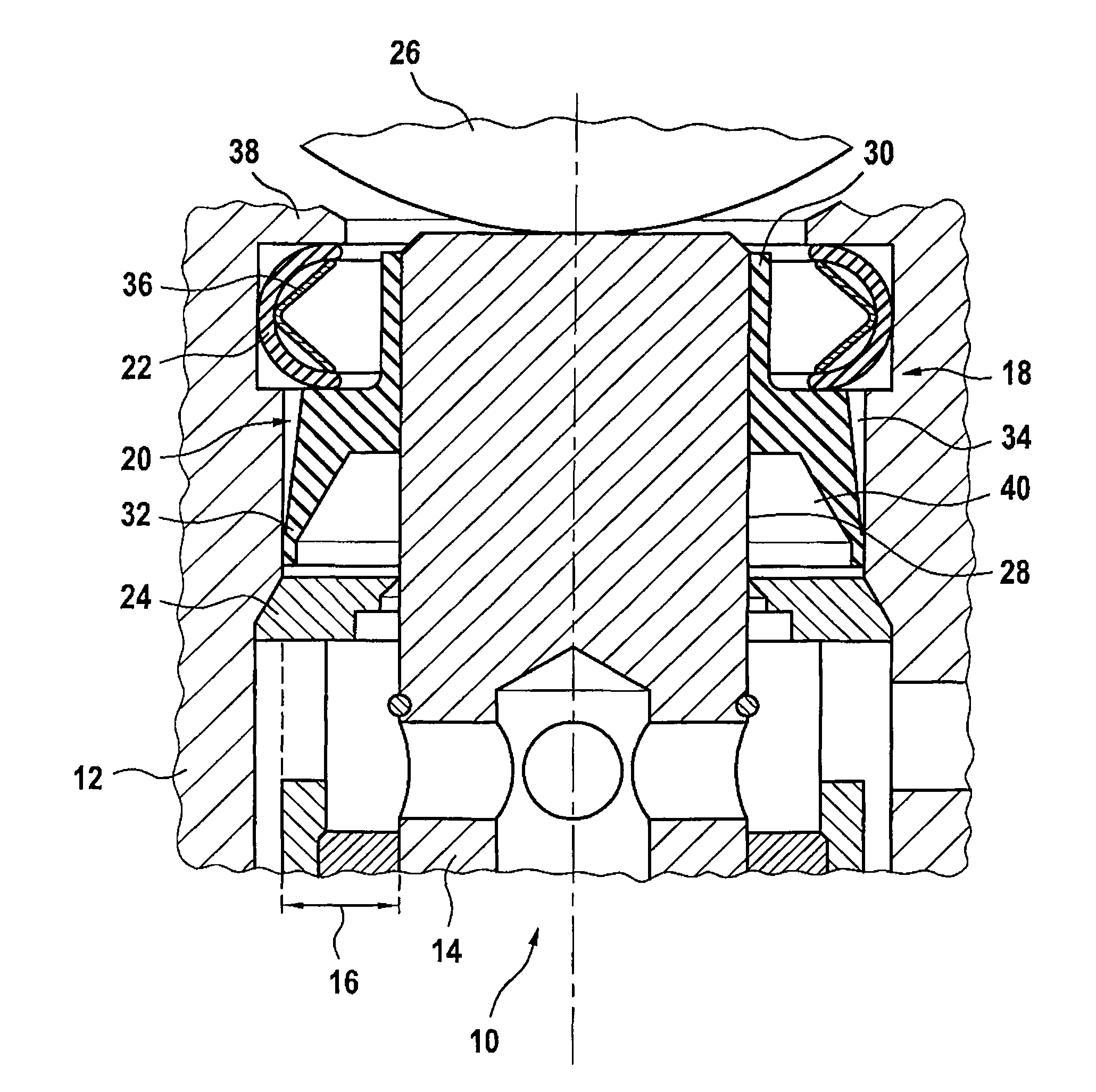
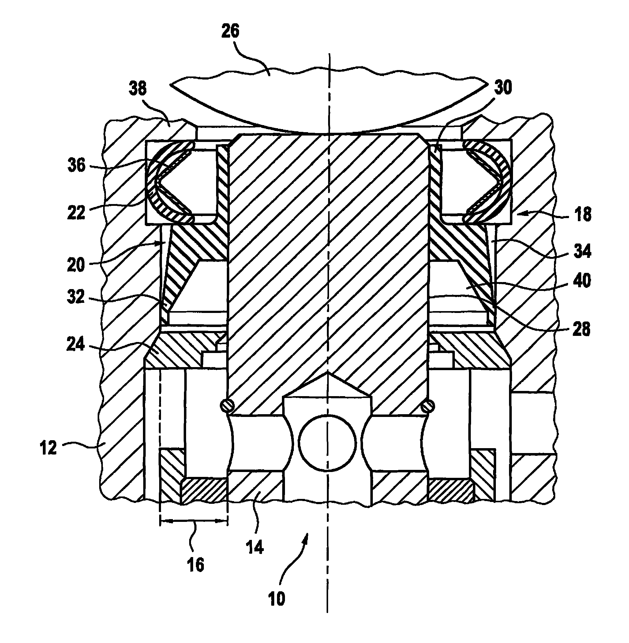
[0026] The drawing shows a piston pump 10 which comprises a housing or cylinder 12 and a piston 14 mounted displaceably in the housing or cylinder. There is a gap 16 between the pump cylinder 12 and the piston 14 . This gap 16 is closed in a fluid-tight manner by means of a sealing device 18 . The sealing device 18 comprises a high-pressure seal 20 and a low-pressure seal 22 as sealing elements. The sliding movement of the piston 14 is substantially guided by a guide ring 24 .

[0027] During operation, the piston 14 is driven by an eccentric 26 . For this purpose, the eccentric 26 therefore presses against an end face of the piston 14 , thereby pushing the piston axially into the housing bore or the pump cylinder 12 and thus carrying out the delivery stroke. For the suction stroke following the delivery stroke, the piston 14 is pushed axially out of the pump cylinder 12 by the spring force of a spring (not shown). As a result, the fluid to be delivered, in the exemplary e...


PUM


Abstract

The invention relates to a piston pump and a hydraulic device of a vehicle brake system, and a vehicle brake system. The piston pump (10) of the vehicle brake system comprises a pumping cylinder (12) and a piston (14) capable of performing mobile support in the pumping cylinder (12). The piston is sealed relative to the pumping cylinder (12) in a fluid-tight manner through sealing devices (18) which can be divided into high-pressure sealing members (20) and low-pressure sealing member (22).

Description

technical field [0001] The invention relates to a piston pump for a vehicle brake system, which has a pump cylinder and a piston movably mounted in the pump cylinder, which is fluid-tight with respect to its drive side by means of a sealing device. way sealed. The invention also relates to a hydraulic device for a vehicle brake system with such a piston pump and a vehicle brake system with such a piston pump. Background technique [0002] Hydraulic devices are an integral part of modern vehicle braking systems, which are used in motor vehicles such as passenger cars or trucks to provide controlled brake pressure. For metering the brake pressure, the hydraulic system has a pump with a plurality of pump elements. Each pump element is usually designed as a piston pump in which a piston is displaceably mounted in a pump cylinder. The drive to the piston is via an eccentric mounted on a shaft driven by an electric motor. The piston moves in and out in the delivery chamber in ...

Claims


Application Information

Patent Timeline
IPC IPC(8): F04B53/16F04B53/02
CPCB60T8/4031F04B1/0448F04B1/0408
Inventor R 布劳恩
Owner ROBERT BOSCH GMBH
Features
  • R&D
  • Intellectual Property
  • Life Sciences
  • Materials
  • Tech Scout
  • Unparalleled Data Quality
  • Higher Quality Content
  • 60% Fewer Hallucinations
Learn More