Structural improvement of engine connecting rod

A technology of engine connecting rods and connecting rods, which is applied in the direction of connecting rods, mechanical equipment, shafts and bearings, etc., can solve the problems of reducing the service life of piston pins, difficult lubrication of lubricating oil, and large impact force of crankshaft, etc., to achieve impact force small effect

Inactive Publication Date: 2011-06-08
苏州麦格特发动机有限公司
View PDF5 Cites 10 Cited by
  • Summary
  • Abstract
  • Description
  • Claims
  • Application Information

AI Technical Summary

Problems solved by technology

[0002] At present, in the connecting rod mechanism of many domestic diesel engines, the connecting rod only plays the function of energy conversion when it is working. Since the big end of the connecting rod body is connected to the crankshaft, and the small end is connected to the piston, when the engine is running at 1500r/ When min rotates, there will be great friction and impact at the joint between the crankshaft and the big end of the connecting rod body and the small end of the connecting rod body and the piston pin. If the

Method used


Image

  • Structural improvement of engine connecting rod
  • Structural improvement of engine connecting rod
  • Structural improvement of engine connecting rod

Examples


Embodiment

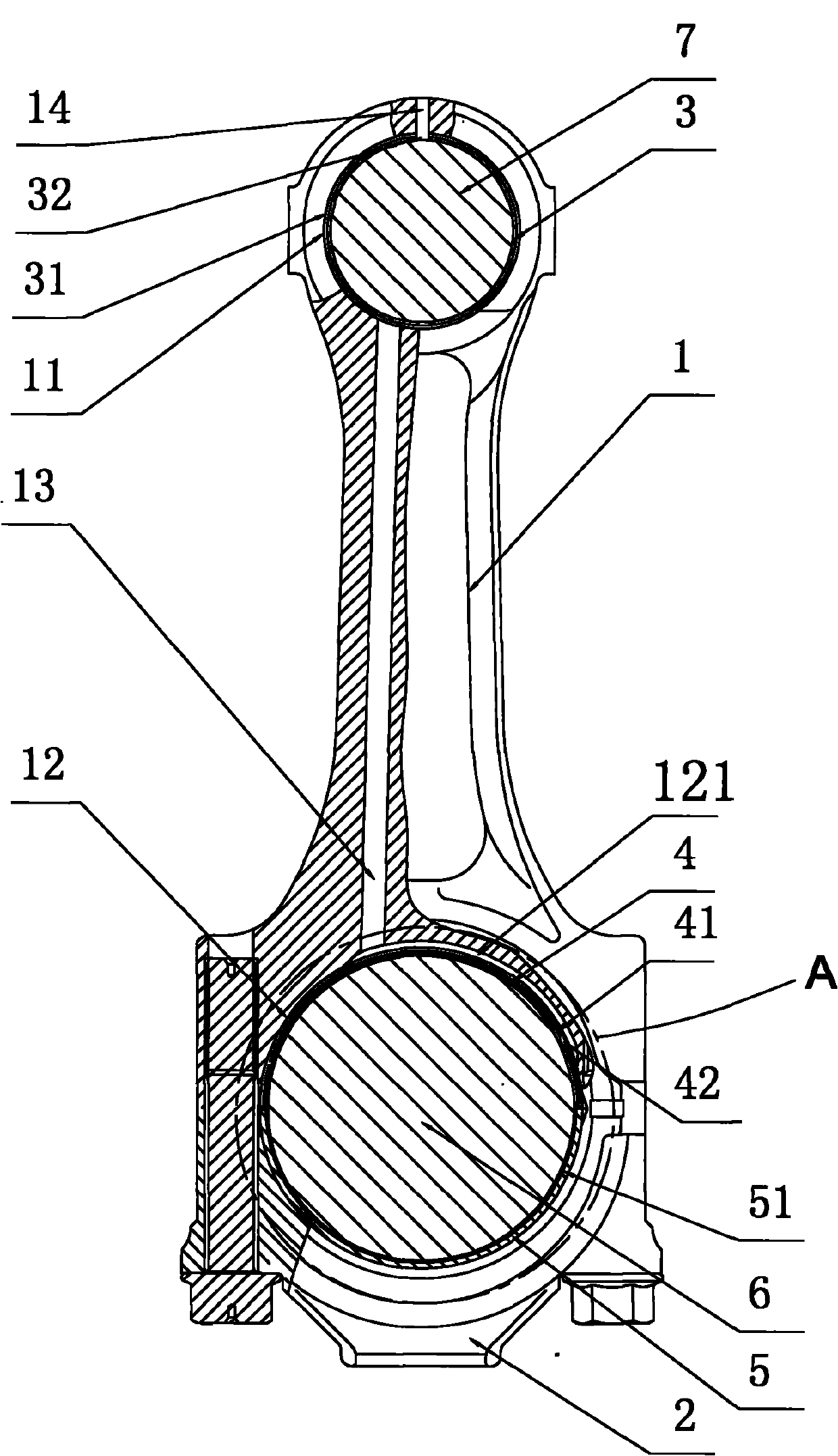
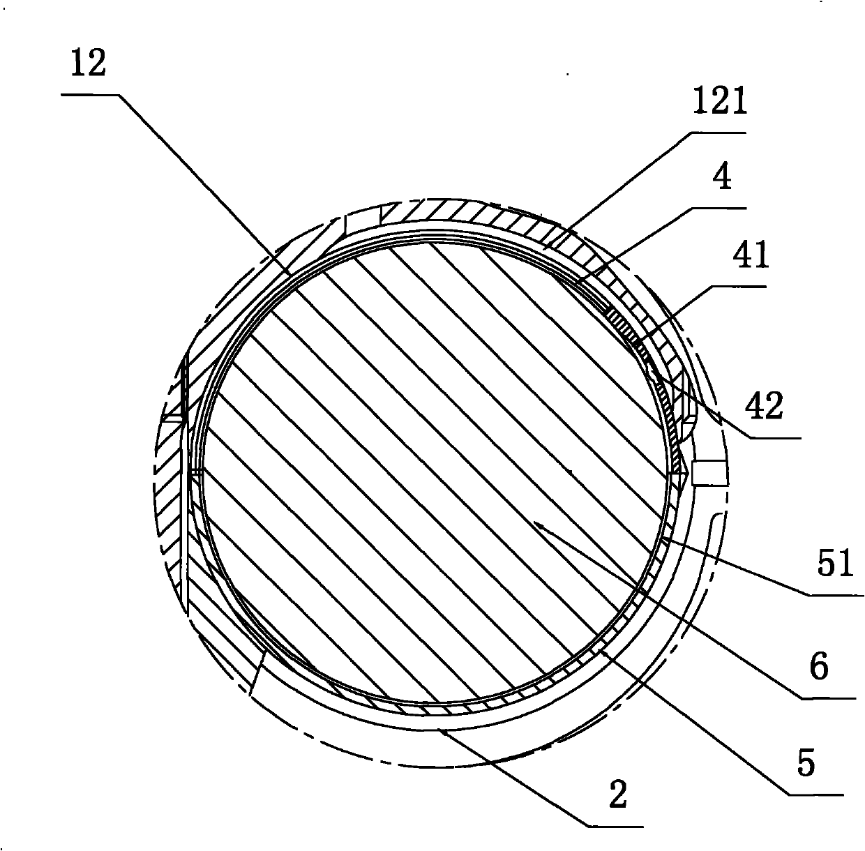
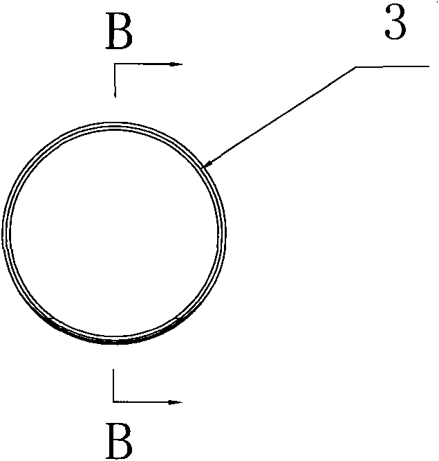
[0015] Embodiment: An improved engine connecting rod structure. The connecting rod includes a connecting rod body 1, a connecting rod cover 2, a bushing 3, an upper bearing bush 4, and a lower bearing bush 5. Based on the direction of use, the big end of the connecting rod body is far away from the small end The end side is detachably connected with the connecting rod cover 2, the small end of the connecting rod body 1 is provided with a piston pin hole 11, the large end and the connecting rod cover together form a crank shaft hole 12 in the same direction as the piston pin hole 11, and the bushing 3 Fixedly inserted into the piston pin hole 11 at the small end of the connecting rod body, the upper bearing bush 4 and the lower bearing bush 5 are radially combined to form a ring shape and inserted into the crank shaft hole 12 at the big end of the connecting rod body, the lower bearing bush 5 The inner side wall is provided with a semicircular concave first oil groove 51, and th...


PUM


Abstract

The invention discloses structural improvement of an engine connecting rod. A big end of a connecting rod body is detachably and fixedly connected with a connecting rod cover to form a crank shaft hole; a bushing is fixedly inserted into a piston pin hole at a small end of the connecting rod body; an upper bearing bush and a lower bearing bush are inserted into the crank shaft hole; the inner walls of the upper bearing bush and the lower bearing bush are provided with a second minor arc-shaped concave oil groove and a first semicircular concave oil groove which are communicated with each other respectively; the second oil groove of the upper bearing bush is provided with a first oil hole in the radial direction; the inner wall of the crank shaft hole of the connecting rod body is provided with a third arc-shaped concave oil groove which is communicated with the first oil hole; the outer wall of a bushing is provided with a fourth concave annular oil groove; the inner wall of a fourth oil groove is provided with at least one radial through hole; and the connecting rod body is provided with at least one oil way which is communicated with the third oil groove and the fourth oil groove respectively. In the structural improvement, lubricating oil in a crank shaft can be led into the bushing, so that the junction of the connecting rod and a piston pin and the junction of the connecting rod and the crank shaft are fully lubricated, the connecting rod produces small impact force to the crank shaft during reciprocating motion, and the upper bearing bush, the lower bearing bush, the connecting rod and the bushing have long service life.

Description

technical field [0001] The invention relates to an engine connecting rod, in particular to an improved structure of the engine connecting rod. Background technique [0002] At present, in the connecting rod mechanism of many domestic diesel engines, the connecting rod only plays the function of energy conversion when it is working. Since the big end of the connecting rod body is connected to the crankshaft, and the small end is connected to the piston, when the engine is running at 1500r / When min rotates, there will be great friction and impact at the joint between the crankshaft and the big end of the connecting rod body and the small end of the connecting rod body and the piston pin. If the lubrication is insufficient, the piston pin and the upper and lower parts will be greatly reduced. The service life of the bearing bush, because the above connection is a clearance fit, the engine is currently lubricating it by spraying oil on the outside of its axial end face. This me...

Claims


Application Information

Patent Timeline
IPC IPC(8): F16C7/02
Inventor 陈伯林
Owner 苏州麦格特发动机有限公司
Why Eureka
Try Eureka