
Microwave bandwidth folding and receiving method

A receiving method and bandwidth technology, applied in the field of receiving broadband microwave pulse signals, to achieve the effect of easy manufacture

Inactive Publication Date: 2011-06-08
CHENGDU LATEST ELECTRONICS TECH
View PDF3 Cites 2 Cited by
  • Summary
  • Abstract
  • Description
  • Claims
  • Application Information

AI Technical Summary

Problems solved by technology

[0003] The purpose of the present invention is to propose a microwave bandwidth folding method to adapt to the dense and complex radar signal environment in view of the defects and deficiencies of the existing receiving methods

Method used


Image

  • Microwave bandwidth folding and receiving method
  • Microwave bandwidth folding and receiving method
  • Microwave bandwidth folding and receiving method

Examples


Embodiment Construction

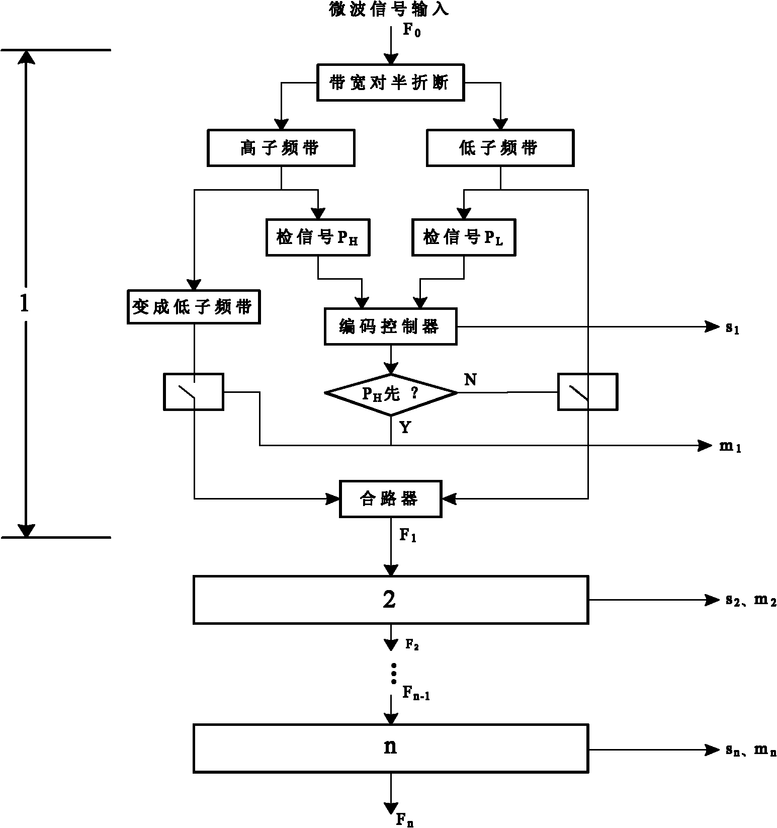
[0020] Further describe technical scheme of the present invention below in conjunction with embodiment: as figure 1 , the microwave bandwidth folding receiving method is: the input frequency band (F 0 ) bandwidth (F W0 ) is broken in half to form high and low sub-bands, and the high sub-band is moved down to the low sub-band; under the control of folding code, the low sub-band where the output signal is located; at the same time, the video pulse is detected from the high and low sub-bands The sequence of the output signal flag (s 1 ) and folding code (m 0 ). The folder folds once, and the bandwidth is reduced by 1 times. Through bandwidth step-by-step folding, the output normalized error radio frequency (F OUT ), characteristic frequency (m 1 m 2 …m n ) and absolute frequency (see Equation 18).

[0021] For the following application, the microwave signal symbols are explained as follows:

[0022] f i : Input / output frequency band (rate), that is, frequency range, i=...


PUM


Abstract

The invention discloses a microwave bandwidth folding and receiving method, comprising: folding the bandwidth of an input band in half to form high and low sub-bands; shifting down the high sub-band to the low sub-band; outputting the low sub-band in which a signal is positioned under the control of a folding code; detecting the sequence of video pulses simultaneously from the high and low sub-bands; and outputting the signal mark (s1) and the folding code (m0). Every time the folder folds, the bandwidth is reduced by double. The normalized error radio frequency, characteristic frequency and absolute frequency are output by folding the bandwidth step by step. The invention has advantages of wide band, good frequency selectivity as well as an instantaneous frequency measurement function without being interfered by overlapped signals. The intercept probability is close to 100%. Due to output normalization, fine frequency measurement becomes possible and a wideband-based digital receiver can be directly obtained. In the invention, conventional components are organically combined and are easy to manufacture.

Description

technical field [0001] The invention relates to the reception of broadband microwave pulse signals, in particular to a microwave bandwidth folding reception method. Background technique [0002] At present, there are roughly the following microwave receiving methods: crystal video receiving method, heterodyne receiving method, instantaneous frequency measurement receiving method, channelized receiving method, micro-sweep (compression) receiving method and acousto-optic (Bragg box) receiving method . The crystal video receiving method cannot output frequency information, and the overlapping signal is wrong. The heterodyne reception method has a narrow frequency band and a low probability of interception, especially for frequency-agile signals. The instantaneous frequency measurement receiving method often outputs wrong frequencies for frequency diversity signals and overlapping signals, and cannot give signs. The channelized reception method is difficult to process the out...

Claims


Application Information

Patent Timeline
Patent Type & Authority Applications(China)
IPC IPC(8): H04B1/16
Inventor 周绍槐杨松
Owner CHENGDU LATEST ELECTRONICS TECH
Learn More