Shear elastic wave on-line anti-scaling and descaling system and anti-scaling and descaling method
A shear elastic and anti-scaling technology, applied in the field of scale removal and anti-scaling, can solve the problems of short service life of heat exchangers, lower production efficiency, narrow application range, etc., and achieve fewer failure points, long service life, and extremely Effect
- Summary
- Abstract
- Description
- Claims
- Application Information
AI Technical Summary
Problems solved by technology
Method used
Image
Examples
Embodiment 1
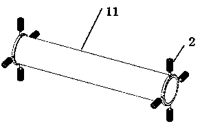
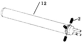
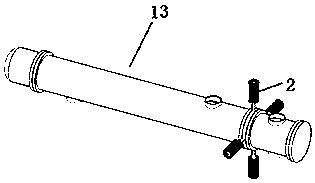
[0053] This example is the application of the scale removal and anti-scaling method using the shear elastic wave online anti-scaling and descaling system on the shell-and-tube heat exchanger: the shell-and-tube heat exchanger is the most commonly used heat exchange equipment in the process industry , according to different application methods, some are tube-side fouling, and some are shell-side fouling. In areas with relatively mild fouling, conventional chemical dosing technology or electronic anti-scaling and descaling technology are effective, but in the actual production field, there are many heat exchangers with very serious fouling, and the heat exchangers have been running for more than 20 days Most of the heat exchangers will be blocked and need to be shut down for maintenance and cleaning, seriously affecting production and causing a lot of energy waste. For example, the technology of the present invention is applied to a sewage evaporator or a reboiler with serious f...
Embodiment 2
[0058] In this example, the application of the scale removal and scale prevention method using the shear elastic wave online scale prevention and scale removal system on pipes, valves and small shell-and-tube heat exchangers:
[0059] In the industrial production process, pipes, valves and small shell-and-tube heat exchangers are often blocked due to scaling or scarring. as follows Figure 4 As shown, the small shell-and-tube heat exchanger 14 is vertically connected with the transducer 2 by a fixture. Such as Figure 5 As shown, the transducer 2 is connected to a small shell-and-tube heat exchanger 15 at an angle.
Embodiment 3
[0061] see Figure 6 In this embodiment, the plate heat exchanger 6 includes several heat exchange plates 61, wave vibration rods 68, front splints 62 and rear splints 63, and one end of the wave vibration rods 68 is equipped with at least one transducer 2, wherein A plurality of heat exchange plates 61 form a heat exchange plate bundle in the frame of the heat exchanger equipment, and each heat exchange plate 61 is closely connected with the vibration rod 68. The heat exchanger equipment frame is composed of a front splint 62 and a rear splint 63. The heat exchange plate bundle is arranged between the front splint 62 and the rear splint 63. The front splint 62 and the rear splint 63 are provided with a thermal fluid inlet 64, a heat Fluid outlet 65 , cold fluid inlet 66 , cold fluid outlet 67 . And the vibration rod 68 also passes through the front splint 62 and the rear splint 63 with a gap. The working principle is that the energy of the shear elastic wave of the transduc...
PUM
 Abstract
Description
Claims
Application Information
 - R&D
- Intellectual Property
- Life Sciences
- Materials
- Tech Scout
- Unparalleled Data Quality
- Higher Quality Content
- 60% Fewer Hallucinations
Browse by: Latest US Patents, China's latest patents, Technical Efficacy Thesaurus, Application Domain, Technology Topic, Popular Technical Reports.
© 2025 PatSnap. All rights reserved.Legal|Privacy policy|Modern Slavery Act Transparency Statement|Sitemap|About US| Contact US: help@patsnap.com


