
Novel wireless electric hair drier

A radio, a new type of technology, used in a new type of wireless hair dryer. It can solve the problem that the battery cannot reach the hair dryer, and achieve the effect of simple structure, avoiding stumbling, and preventing hair damage.

Inactive Publication Date: 2011-06-15
刘建波
View PDF1 Cites 14 Cited by
  • Summary
  • Abstract
  • Description
  • Claims
  • Application Information

AI Technical Summary

Problems solved by technology

[0003] The purpose of the present invention is to provide a new type of wireless hair dryer whose electric motor and heating element are separately powered, which overcomes the problem that the current storage battery cannot meet the actual needs of the hair dryer, and can achieve the goal of wireless use

Method used


Image

  • Novel wireless electric hair drier
  • Novel wireless electric hair drier
  • Novel wireless electric hair drier

Examples


Embodiment 1

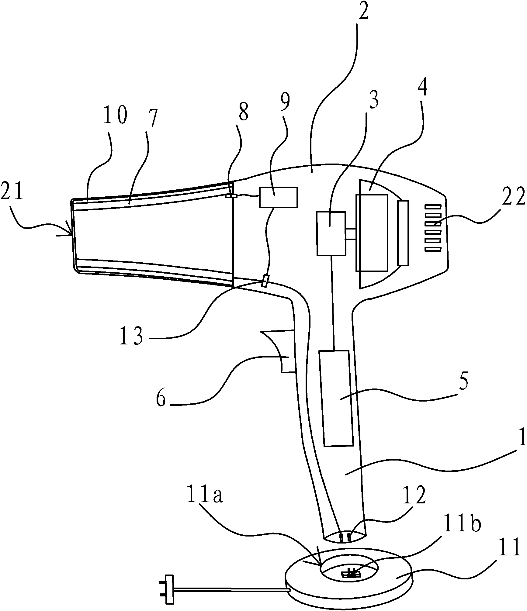
[0027] Such as figure 1 As shown, the new wireless hair dryer includes a housing 2 with an air inlet 22 and an air outlet 21, a handle 1 is extended on the housing 2, and a motor 3 and a fan 4 are installed on the air duct between the air inlet 22 and the air outlet 21. A storage battery 5 is housed in the handle 1, and a switch 6 is electrically connected between the storage battery 5 and the motor 3. The switch 6 is arranged on the side wall of the handle 1. The hair dryer also includes a heat accumulator 7 and is connected with the heat accumulator 7 and can The heating device heated by the heater 7, the heat accumulator 7 in the present embodiment is a ceramic heater, and the ceramic heater is fixed on the inner wall of the air outlet channel at the air outlet 21, between the ceramic heater and the inner wall of the air outlet channel A layer of asbestos 10 is fixed between them. The housing 2 is also provided with a temperature sensor 8 for detecting the temperature info...

Embodiment 2

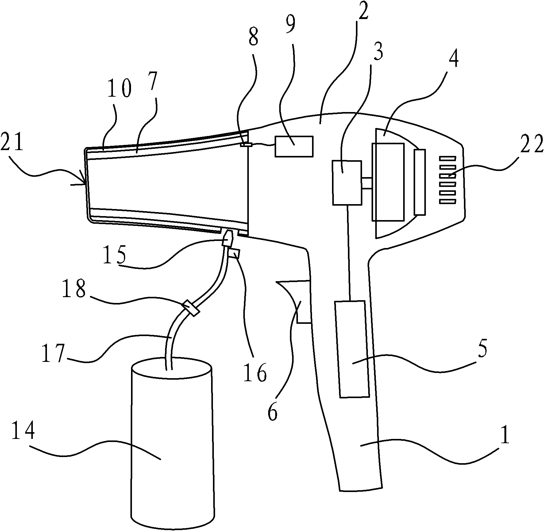
[0032] Such as figure 2 As shown, the difference between this embodiment and Embodiment 1 is that in structure, its regenerator 7 is a honeycomb-shaped ceramic heating ring, and its heating device includes an external gas barrel 14, with an ignition switch The burner 15 of 16, the gas pipe 17 connecting the gas barrel 14 and the burner 15 and the electromagnetic valve 18 arranged on the gas pipe 17, the burner 15 passes through the shell wall of the shell 2 and faces the outer wall of the ceramic heating ring, electromagnetic The valve 18 is electrically connected with the temperature regulator 9; in terms of working principle, the ceramic heating ring is heated by igniting the gas from the gas barrel 14 through the ignition switch 16. When the temperature of the ceramic heating ring reaches the requirement, the temperature regulator 9 is to stop the combustion heating by controlling the closing of the electromagnetic valve 18, so that the ceramic heating ring is no longer co...

Embodiment 3

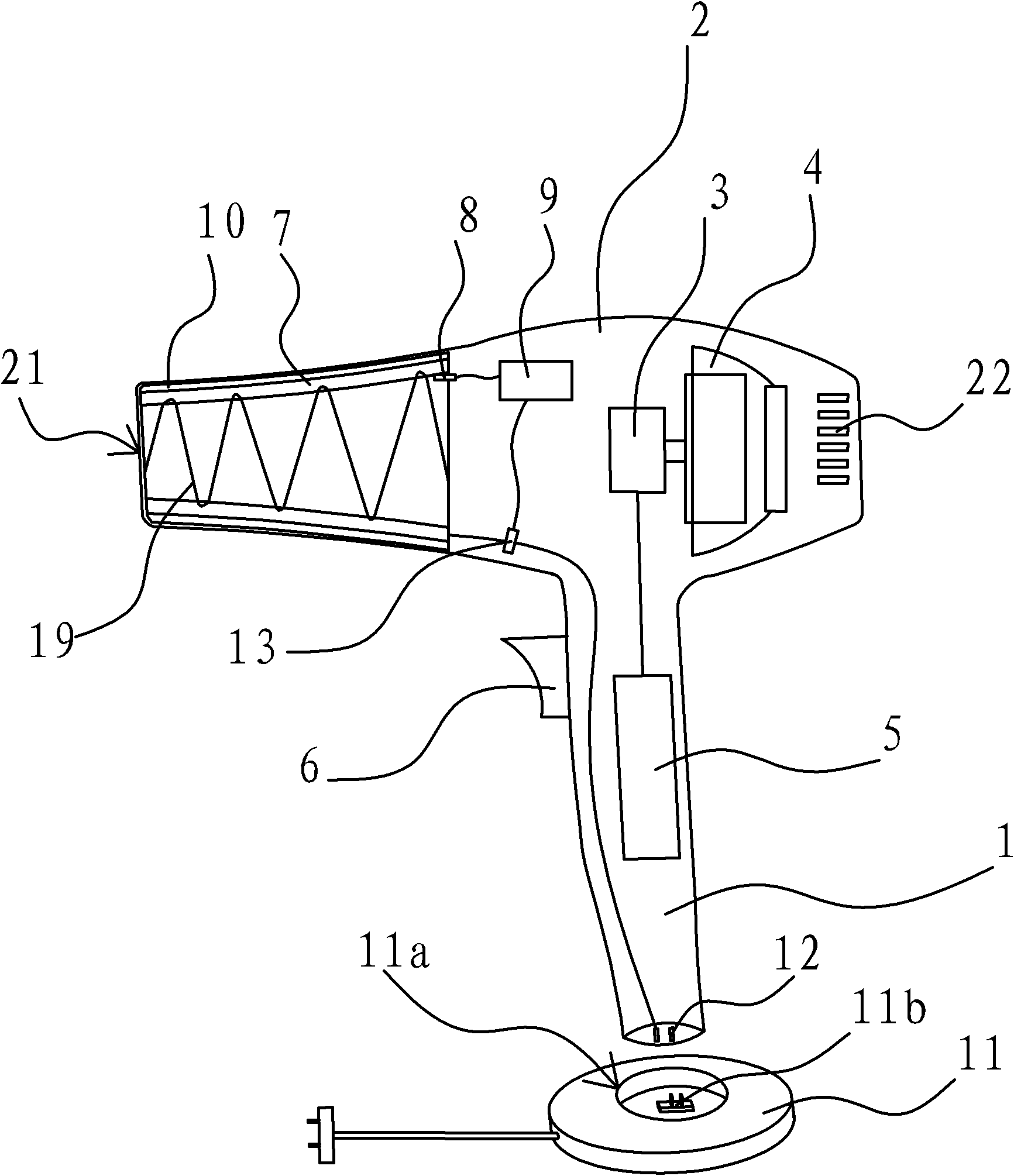
[0034] Such as image 3 As shown, the difference between the present embodiment and the first embodiment is that: structurally, the heat accumulator 7 is a hollow device with a back-shaped shape, and its back-shaped part is equipped with heat-conducting oil and heating wire 19, and the heating wire 19 is encapsulated in the heat-conducting oil Middle; In terms of working principle, the heating wire 19 is connected to the external power supply for heating, the heat transfer oil is heated to store heat, and the wind is heated through the air duct. Other structures and principles are the same as those in Embodiment 1, and will not be repeated here.


PUM


Abstract

The invention relates to a novel wireless electric hair drier, belonging to the technical filed of electric hair driers. The difficulty that the existing storage battery can not satisfy the actual requirement is overcome. The novel wireless electric hair drier comprises a shell which is provided with an air inlet and an air outlet, a heat accumulator and a heating device which is connected with the heat accumulator and can heat the heat accumulator, wherein the shell is extended to form a handle; an air duct between the air inlet and the air outlet is provided with a motor fan assembly; the handle is internally provided with batteries; a switch is electrically connected between the batteries and the motor fan assembly; the switch is arranged on the side wall of the handle; the heat accumulator is fixedly arranged on the inner wall of an air outlet duct which is positioned at the air outlet; the shell is also internally provided with a temperature control element and a temperature regulator, the temperature control element is used for detecting the temperature information of the heat accumulator and the temperature regulator can control whether the heating device works or not; and the temperature regulator is respectively connected with the temperature control element and the heating device electrically. The novel wireless electric hair drier has the advantages of simple structure and wireless and split type functions.

Description

technical field [0001] The invention belongs to the technical field of hair dryers, in particular to a novel wireless hair dryer. Background technique [0002] At present, hair dryers are generally used in beauty salons and hair dryers. When using hair dryers, they are generally plugged into external power sources through wires and plugs to obtain electric power and electric heating effects. The long wires often cause stumbling, especially In beauty salons, people move around frequently and the space is relatively small, and stumbling often occurs. At the same time, the temperature of the air blown by the existing hair dryer cannot be accurately controlled, and can only be roughly controlled by one or two gears of the switch. , because the comfortable temperature required by everyone is not necessarily the same, and if the temperature is too high, it will cause some damage to the hair, so the temperature of the air blown by the hair dryer may be more suitable for this person...

Claims


Application Information

Patent Timeline
Patent Type & Authority Applications(China)
IPC IPC(8): A45D20/10A45D20/12H05B3/02
Inventor 刘建波
Owner 刘建波
Learn More