Fan coil, control device and control method

A fan coil unit and control method technology, applied in heating and ventilation control system, space heating and ventilation control input, control input related to air characteristics, etc., can solve the problem of uneven temperature field and wind field in the room, poor comfort, Solve problems such as medium temperature fluctuations, achieve the effect of improving stability and comfort, improving user comfort, and stable and reliable operation

Active Publication Date: 2020-02-11
NINGBO AUX ELECTRIC
View PDF14 Cites 0 Cited by
  • Summary
  • Abstract
  • Description
  • Claims
  • Application Information

AI Technical Summary

Problems solved by technology

With the improvement of people's living standards, users have put forward higher requirements for the comfort of air conditioners, but the existing fan coil unit has a single control mode and poor comfort, and the main problems are as follows:
[0003] The air outlet temperature is an important comfort index of the air conditioner. If the outlet air temperature is too high or too low, it will directly affect the user experience. At present, when the fan coil unit is working, it is mainly controlled by the relationship between the set temperature and the return air temperature. The switch of the fan and heat transfer medium inlet valve, the temperature of the heat transfer medium is mainly determined by the heat transfer medium provided by the air conditioning refrigeration / heating system, the temperature of the medium entering the fan coil heat exchanger has large fluctuations, which affects the outlet air temperature The stability and suitability of the fan coil unit is not easy to control the outlet air temperature
Moreover, the frequent switching of the fan and the liquid inlet valve will cause the outlet air temperature to be unstable, and the room temperature field and wind field to be uneven, which will affect the user experience
The fan will also generate intermittent noise when it is turned on and off, which will affect the user's sense of hearing and cause discomfort

Method used


Image

  • Fan coil, control device and control method
  • Fan coil, control device and control method
  • Fan coil, control device and control method

Examples


Embodiment Construction

[0052] In order to make the above objects, features and advantages of the present invention more comprehensible, specific embodiments of the present invention will be described in detail below in conjunction with the accompanying drawings.

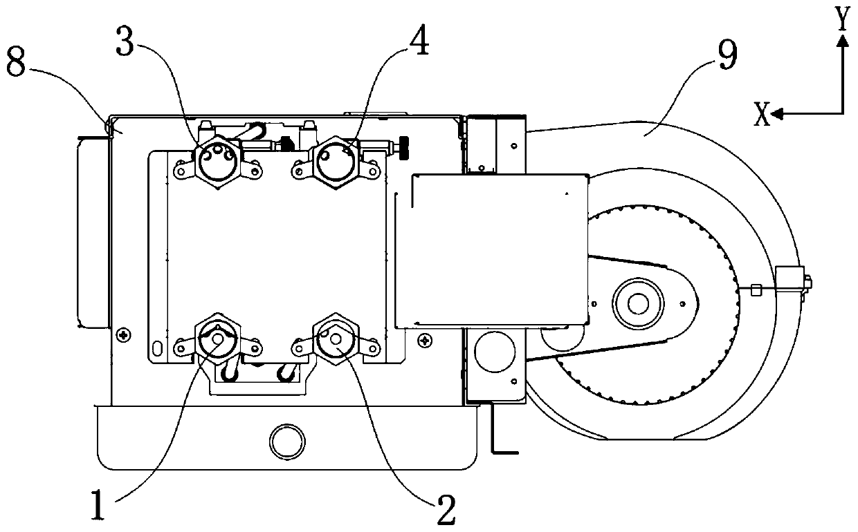
[0053] In the description of the present invention, it should be noted that the terms and nouns in each embodiment, such as "up", "down", "front", "back", "left", "right" and other words indicating orientation, are only In order to simplify the description of the positional relationship based on the drawings in the specification, it does not mean that the components and devices referred to must operate in accordance with the specific orientation and defined operations, methods, and structures in the specification, and such orientation terms do not constitute limitations on the present invention.

[0054] In the drawings of the embodiments of the present invention, a coordinate system XY is set, wherein the positive direction of X represents...


PUM


Abstract

The invention provides a fan coil, a control device and a control method. The control method includes the following steps that an actual return air temperature and an actual air outlet temperature areobtained; a target air outlet temperature is determined according to the actual return air temperature; according to the actual air outlet temperature and the target air outlet temperature, a targetopening of a mixing valve of a cooling medium and a heating medium of the fan coil is determined; and the opening of the mixing valve is adjusted according to the target opening. Compared with the prior art, according to the control method, the air outlet temperature is adjusted by changing the opening of the mixing valve, so that the air outlet temperature is more stable, the comfort of the fan coil is improved, and the user experience is improved.

Description

technical field [0001] The present invention relates to the technical field of air conditioning, in particular to a fan coil control device and control method. Background technique [0002] The fan coil unit is an important terminal device in the central air-conditioning system, which is used to blow out heat-exchanged wind to the environment to adjust the air temperature. With the improvement of people's living standards, users have put forward higher requirements for the comfort of air conditioners, but the existing fan coil unit has a single control mode and poor comfort, and the main problems are as follows: [0003] The air outlet temperature is an important comfort index of the air conditioner. If the outlet air temperature is too high or too low, it will directly affect the user experience. At present, when the fan coil unit is working, it is mainly controlled by the relationship between the set temperature and the return air temperature. The switch of the fan and he...

Claims


Application Information

Patent Timeline
Patent Type & Authority Applications(China)
IPC IPC(8): F24F1/0007F24F11/30F24F11/64F24F11/74F24F11/84F24F11/88F24F110/10
CPCF24F1/0007F24F11/30F24F11/64F24F11/74F24F11/84F24F11/88F24F2110/10Y02B30/70
Inventor 李翱翔
Owner NINGBO AUX ELECTRIC
Why Eureka
Try Eureka