Ventricle drainer

A ventricular drainage and panel technology, applied in the field of ventricular drainage, can solve the problems of backflow at the injection port, affecting the injection process, and failing to improve the efficiency of liquid collection

Active Publication Date: 2011-06-15
苏州新区华盛医疗器械有限公司
View PDF5 Cites 3 Cited by
  • Summary
  • Abstract
  • Description
  • Claims
  • Application Information

AI Technical Summary

Problems solved by technology

[0002] In the blood collection device of existing medical equipment, through such as Figure 7 The collection device shown mainly includes a liquid storage bag 21, a drainage tube 22 sealingly connected with the liquid storage bag 21, and a drainage regulator 23 that can slide outside the overflow tube to control the flow rate. The liquid storage bag 21 is a stretchable spring shape, collect blood by compressing its own liquid storage bag 21, and use a single drainage regulator 23 to control the blood flow rate. In this way, the efficiency of liquid collection can neither be improved nor the safety of liquid collection can be guaranteed; the equipment related to the drainage device is still in the In the original hook-type state, when a patient is sick and needs an IV or injects a medicinal solution in the brain, he simply nails a nail on a high wall or a wooden board, and then hangs the fluid storage bag 21 through a rope. on the nail
In this way, when the liquid storage bag 21 is injected into the human body, it will easily shake left and right due to external collisions, causing air to enter the injection port to cause backflow, and as the liquid medicine in the bottle decreases, the internal pressure will also increase. Even if there is a slight change, for the person undergoing brain injection, a little pressure difference will also have serious consequences. In this way, the liquid storage bag always maintains a certain height, which will affect the normal injection process

Method used


Image

  • Ventricle drainer
  • Ventricle drainer
  • Ventricle drainer

Examples


Embodiment Construction

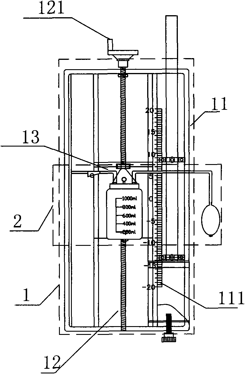
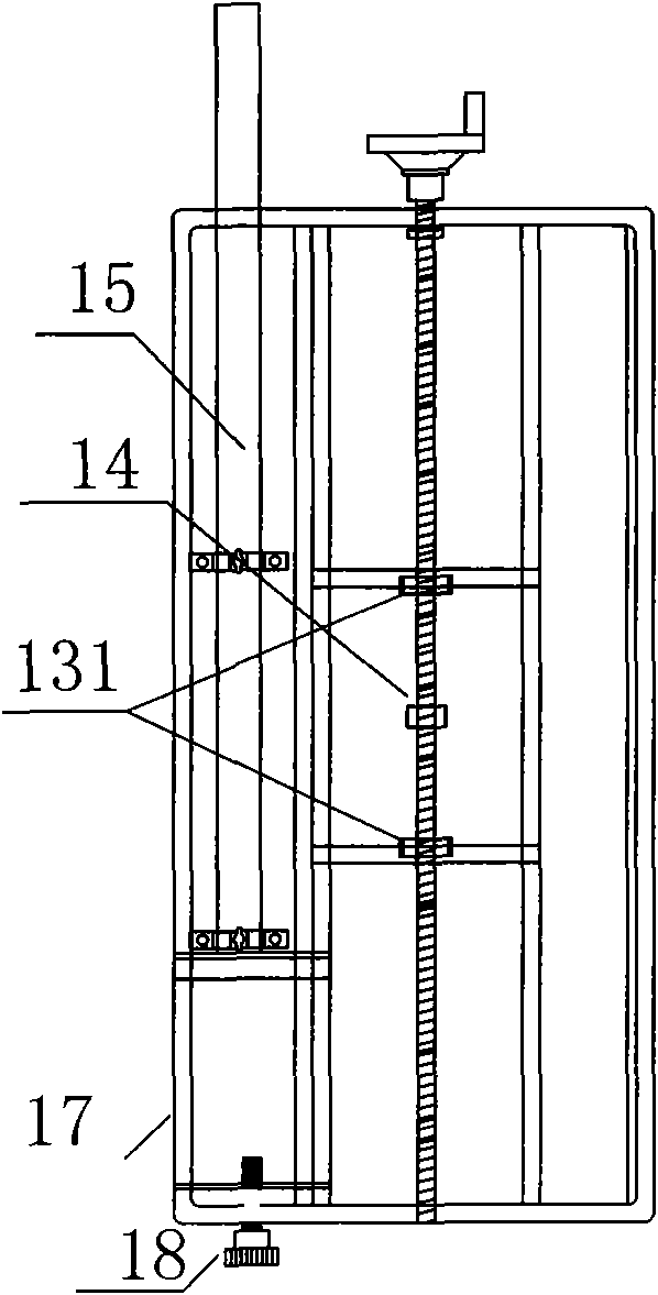
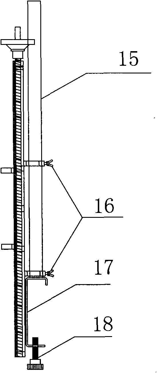
[0019] figure 1 A ventricular drainage device is shown, which is characterized by comprising: a drainage device 1 and a negative pressure liquid collection device 2, wherein the main body of the drainage device 1 is a panel 11, the middle of the panel 11 is hollowed out, and a screw 12 is arranged in the middle of the panel 11 , the head of the screw 12 is equipped with a hand wheel 121, and the screw 12 is connected with a slider 13, which is connected by a screw nut 14; the main body of the negative pressure liquid collection device 2 is a liquid storage bag 21, which is inserted into the drainage tube connected to the entrance of the liquid storage bag 21 22. Put the drainage regulator 23 outside the drainage tube 22, and connect a negative pressure tube 26 at the entrance of the liquid storage bag 21. The other end of the negative pressure tube 26 is sealed and connected with a negative pressure regulating ball 27. A single-phase exhaust valve device 28 is installed in th...


PUM


Abstract

The invention relates to a ventricle drainer which is characterized by comprising a drain device and a negative-pressure liquid collecting device, wherein the main body of the drain device is a panel, the middle of the panel is hollow, the middle of the panel is provided with a screw, the head of the screw is provided with a hand wheel, and a slide block is connected on the screw through a screw nut; and the main body of the negative-pressure liquid collecting device comprises a liquid storage bag, a drain tube and a drain regulator, wherein the drain tube is inserted into the liquid storage bag and is hermetically connected with the inlet of the liquid storage bag, the drain regulator is sleeved outside the drain tube, a negative-pressure tube is hermetically connected with the inlet of the liquid storage bag, the other end of the negative-pressure tube is hermetically connected with a negative-pressure regulation ball, and a single-phase exhaust valve device is installed in the negative-pressure regulation ball. The whole panel is fixed in a proper position by a bed fixing frame, the hand wheel is rotated to regulate the height of the slide block, the single-phase exhaust valve device in the negative-pressure regulation ball enables the inside of the liquid storage bag to generate pressure difference, and liquid smoothly flows into the liquid storage bag through the drain tube, thereby ensuring that the liquid collecting effect is better in a certain pressure range, and the collected person is safe.

Description

technical field [0001] The invention relates to a ventricle drainage device for controlling the height of a drip bottle in a medical device to control the pressure generated by the medicinal liquid flowing into the human body. Background technique [0002] In the blood collection device of existing medical equipment, through such as Figure 7 The collection device shown mainly includes a liquid storage bag 21, a drainage tube 22 sealingly connected with the liquid storage bag 21, and a drainage regulator 23 that can slide outside the overflow tube to control the flow rate. The liquid storage bag 21 is a stretchable spring shape, collect blood by compressing its own liquid storage bag 21, and use a single drainage regulator 23 to control the blood flow rate. In this way, the efficiency of liquid collection can neither be improved nor the safety of liquid collection can be guaranteed; the equipment related to the drainage device is still in the In the original hook-type state,...

Claims


Application Information

Patent Timeline
Patent Type & Authority Applications(China)
IPC IPC(8): A61M5/14A61M5/36A61B5/154
Inventor 吴凌庚
Owner 苏州新区华盛医疗器械有限公司
Why Eureka
Try Eureka