Spinning winding apparatus

A kind of equipment and spinning technology, which is applied in the field of spinning and winding equipment, can solve problems such as the reduction of the mechanical resonance point of the roller, the decline of the quality of the silk thread, and the abnormal vibration of the roller, so as to reduce the number of contacts, improve the quality, and prevent the coarse details of the yarn. the effect produced

Active Publication Date: 2011-06-15
TMT MACHINERY INC
View PDF4 Cites 10 Cited by
  • Summary
  • Abstract
  • Description
  • Claims
  • Application Information

AI Technical Summary

Problems solved by technology

[0005] However, if the length of the roller shaft is increased, the mechanical resonance point of the roller is lowered, so there is a problem that abnormal vibrations are generated on the roller in the operating range during yarn production
[0006] In addition, if the inclination angle of the Nelson roller pair is increased, the thread stretched on the Nelson roller pair may vibrate sometimes, and the thread due to the vibration will interfere with other thread threads that are advancing in parallel, and the stretching point of the thread (the thread is drawn from Yarn roughness caused by fluctuations in the point where the roller is sent out) leads to problems such as deterioration of yarn quality

Method used


Image

  • Spinning winding apparatus
  • Spinning winding apparatus
  • Spinning winding apparatus

Examples


Embodiment Construction

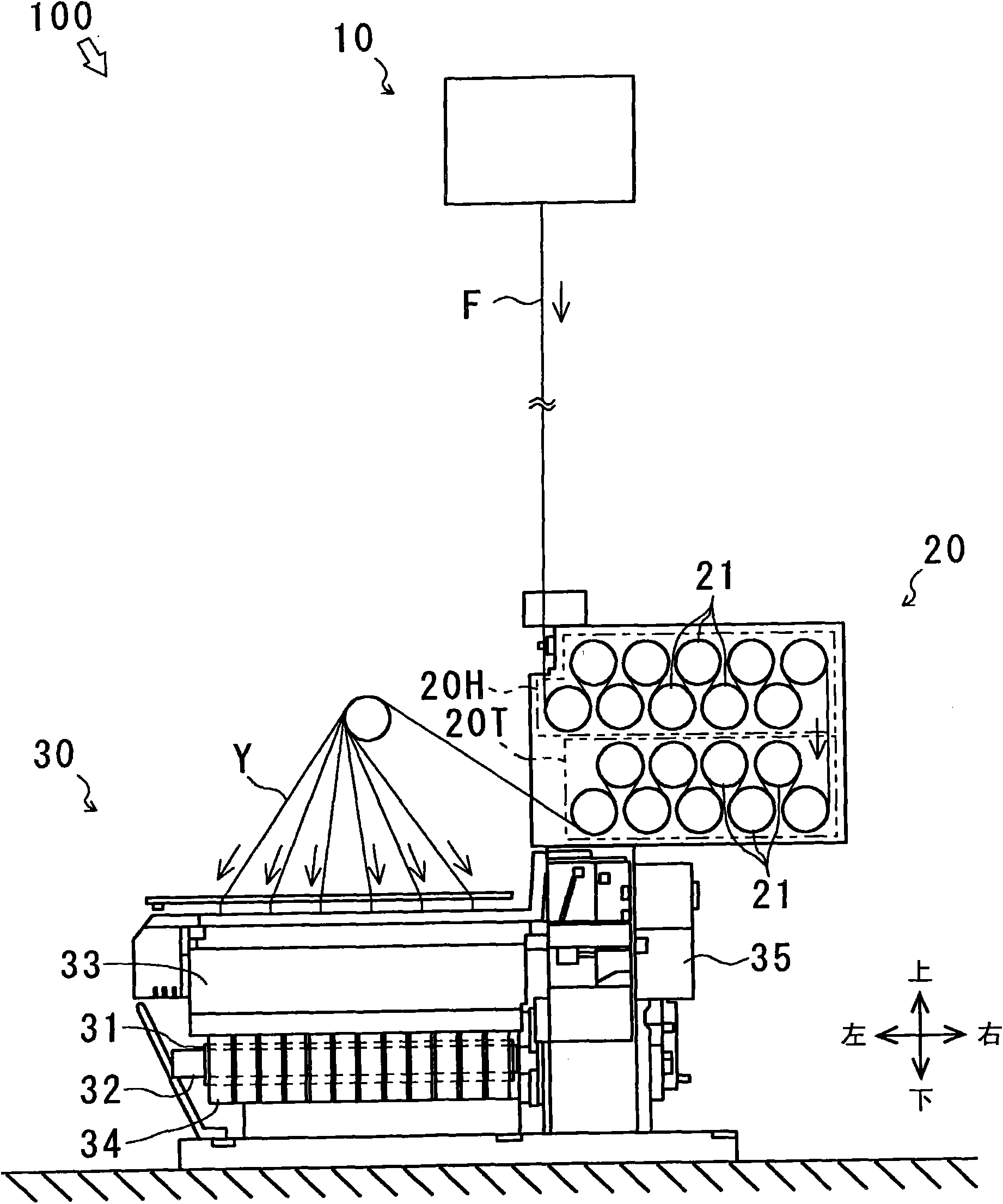
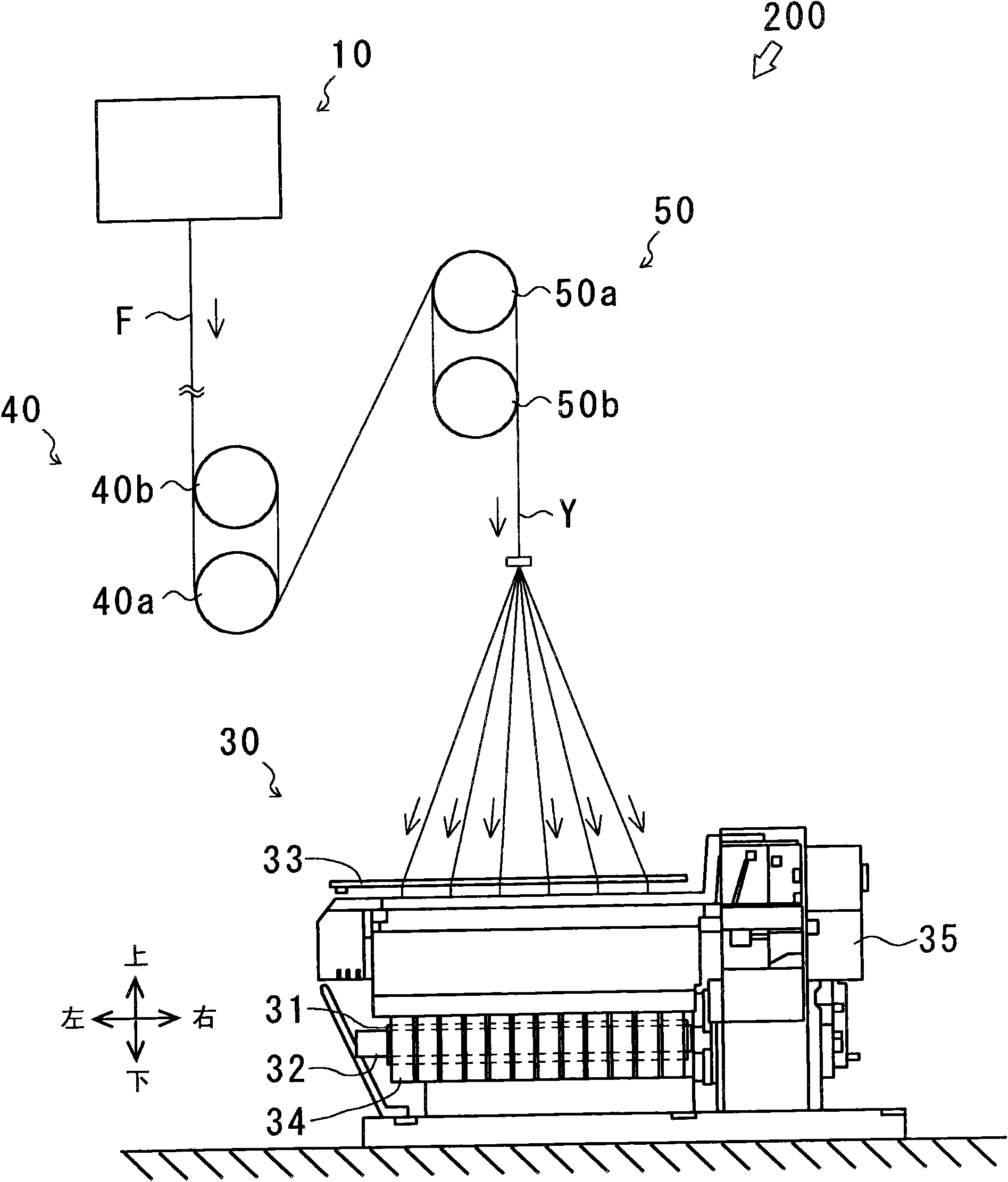
[0042] first use figure 1 The overall structure of the spinning winding equipment 100 according to the first embodiment of the present invention will be described. figure 1 It is a front view showing the overall structure of the spinning winding device 100 . In addition, the acting direction of gravity is defined as an up-down direction, and the axial direction of the bobbin holder shaft 32 included in the winder 30 is defined as a left-right direction. In addition, the arrows shown in the figure indicate the feeding direction of the monofilament F and the yarn Y.

[0043] The spinning and winding equipment 100 is mainly composed of a spinning machine 10 that spins out the single fiber F, a group of wire feed rollers 20 that stretches and heat-sets the yarn Y formed by bundling the single fiber F, and the group of wire feed rolls 20 that will A winding machine 30 for winding the fed yarn Y onto a bobbin 31 is constituted.

[0044]The spinning machine 10 is a device that spi...


PUM


Abstract

The invention provides a spinning winding apparatus capable of preventing abnormal vibration of rollers, interference of silk yarns and generation of yarn thick and thin nodes, and improving quality of manufactured silk yarns even under a condition of increasing filaments spun by a spinning machine and manufactured silk yarns. The spinning winding apparatus (100) provided with a spinning machine (10) spinning filaments and a winding machine (30) winding a plurality of silk yarns (Y) formed by binding the filaments to each bobbin (31) is provided with: a filament feeding roller group (20) provided with a plurality of rollers (21) transmitting the plurality of silk yarns (Y) via hanging and rotating the silk yarns (Y), the filament feeding roller group (20) comprises a parallel roller group(20P) with rotary shafts of the rollers (21) parallel to each other, the respective roller (21) forming the parallel roller group (20P) respectively contacts with the plurality of silk yarns (Y) in acontact length less than the circumference of the roller (21).

Description

technical field [0001] The present invention relates to the technology of spinning winding equipment. More specifically, it relates to a technique for improving the quality of yarn produced by a spinning winding facility. Background technique [0002] In the past, we have known a spinning and winding device for preheating by bundling single fibers spun from a spinning machine to form a plurality of filaments, and winding these plurality of filaments over a pair of rollers (see, for example, Patent No. Document 1, Patent Document 2). In such spinning winding equipment, since a plurality of yarns are wound multiple times over a pair of rollers, it is necessary to prevent interference between yarns, and it is indispensable to use a pair of so-called Nelson rollers. [0003] In addition, we also know a spinning and winding device that stretches a plurality of preheated filaments separately, and then winds the plurality of filaments over a pair of rollers, and performs heat set...

Claims


Application Information

Patent Timeline
Patent Type & Authority Applications(China)
IPC IPC(8): D01D7/00D01D10/02B65H54/02
CPCD01D10/02B65H2701/38B65H2601/524B65H51/08B65H2701/3132D01D13/02
Inventor 桥本欣三
Owner TMT MACHINERY INC
Why Eureka
Try Eureka