Check patentability & draft patents in minutes with Patsnap Eureka AI!

Fuel injection valve

A technology for fuel injection valves and fuels, which is applied to fuel injection devices, charging systems, engine components, etc., and can solve problems such as insufficient improvement of valve opening or closing responsiveness

Active Publication Date: 2011-06-15
HITACHI ASTEMO LTD
View PDF2 Cites 9 Cited by
  • Summary
  • Abstract
  • Description
  • Claims
  • Application Information

AI Technical Summary

Problems solved by technology

[0006] In the above-mentioned prior art, the fluid resistance of the fuel passage provided in the armature affects the operation of the armature, and the responsiveness at the time of valve opening or closing cannot be sufficiently improved.

Method used


Image

  • Fuel injection valve
  • Fuel injection valve
  • Fuel injection valve

Examples


Embodiment Construction

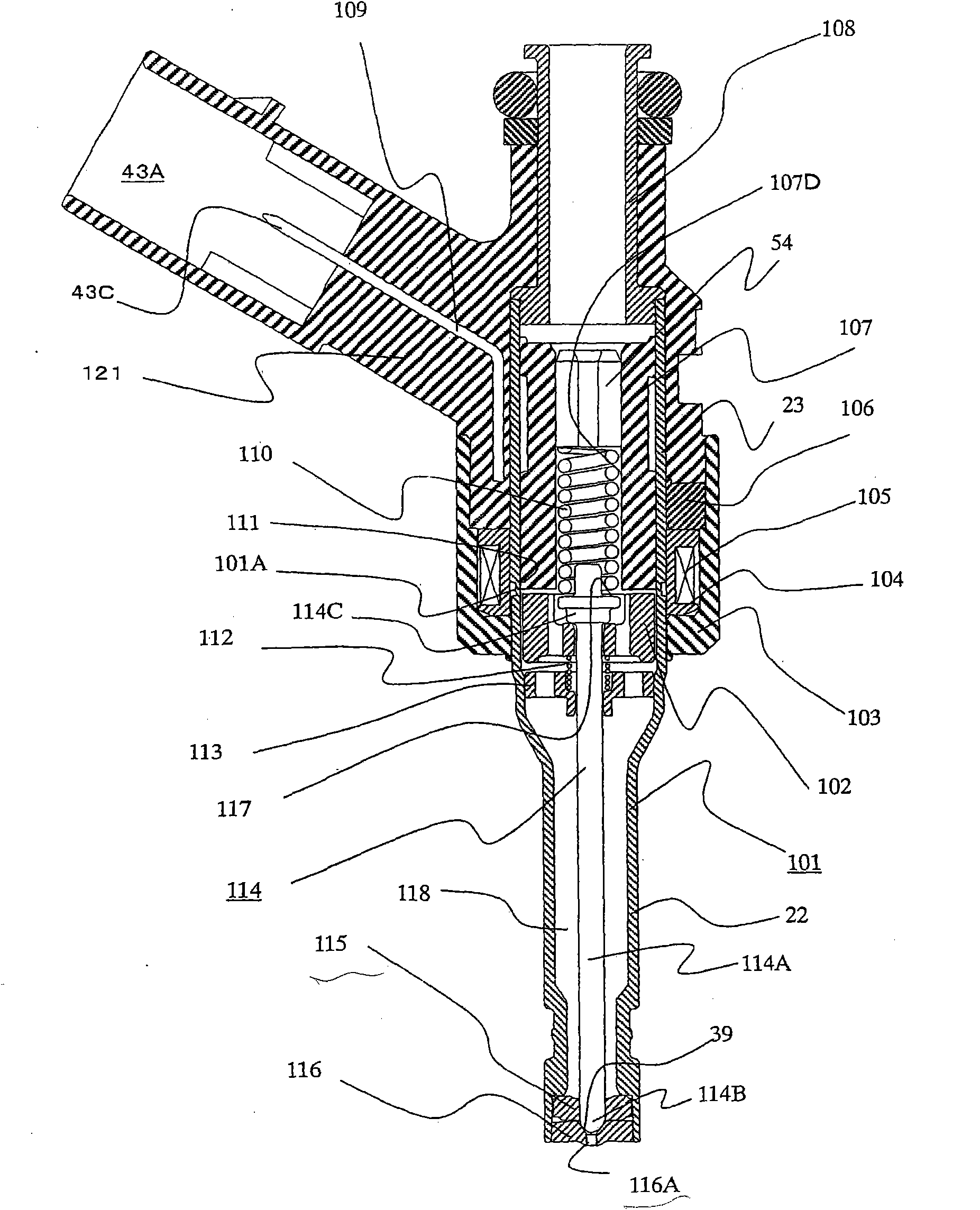
[0021] Below, use figure 1 , figure 2 The overall configuration of the embodiment will be described.

[0022] figure 1 It is a longitudinal sectional view of the fuel injection valve of the embodiment. figure 2 yes figure 1 is a partial enlarged view showing detailed features of the fuel injection valve of the embodiment.

[0023] The nozzle pipe 101 made of a metal material includes a small-diameter cylindrical portion 22 with a small diameter and a large-diameter cylindrical portion 23 with a large diameter, both of which are connected by a conical cross-sectional portion 24 .

[0024] A nozzle body is formed at the front end portion of the small-diameter cylindrical portion 22 . Specifically, a guide member 115 for guiding fuel to the center and an orifice 116 having a fuel injection port 116A are sequentially inserted into the cylindrical portion formed inside the front end portion of the small-diameter cylindrical portion. It is fixed to the cylindrical part by we...


PUM


Abstract

The invention provides a fuel injection valve, which is used for shortening valve-closing delay time caused by fluid resistance of a fuel passage and reducing minimum injection quantity in an injector of an internal combustion engine. An armature is attracted to the end face of a fixed core of which the center is provided with the fuel passage by electromagnetic force, and a valve body which is driven together with the armature is controlled to open and close a fuel injection port; the center of the upper end face of the armature is provided with a fuel storage position; a through hole of which one end is provided with an opening towards the fuel storage position and which extends along the axial direction, and the fuel passage which extends to the outer side of the radius direction from the fuel storage position and supplies a fuel to a magnetic gap between the upper end face of the armature and the lower end face of the fixed core are formed on the armature; in addition, the opening of the through hole on the upper end face of the armature is at least partially opposite to a fuel lead-in port of the fixed core; furthermore, the opening part of the through hole is provided with a fuel lead-in part for capturing the fuel flowing from the central side to the outer side of the armature and leading the fuel in the through hole.

Description

technical field [0001] The present invention relates to a fuel injection valve for an internal combustion engine, in particular to a fuel injection valve which uses an electromagnetically driven movable element to open and close a fuel passage. Background technique [0002] As a conventional fuel injection valve of this type, JP-A-11-22585 discloses a method for reducing fluid resistance when the armature moves and improving valve operation efficiency by providing longitudinal grooves on the outer peripheral portion of the armature. Responsiveness. [0003] It is described in JP-A-58-178863 or JP-A-2006-22721 that the movable element is composed of a cylindrical armature, a plunger located at the center of the armature, and a device. In the valve body at the front end of the plunger, a magnetic gap is provided between the end face of the fixed iron core and the end face of the armature having a fuel introduction hole for introducing fuel in the center, and a magnetic flux i...

Claims


Application Information

Patent Timeline
Patent Type & Authority Applications(China)
IPC IPC(8): F02M51/06
Inventor 早谷政彦安部元幸石川亨久保田荣一小渡武彦
Owner HITACHI ASTEMO LTD
Features
  • R&D
  • Intellectual Property
  • Life Sciences
  • Materials
  • Tech Scout
  • Unparalleled Data Quality
  • Higher Quality Content
  • 60% Fewer Hallucinations
Learn More