Energy-collecting speed-increasing reverse-rotating lift-drag composite type vertical shaft wind power machine
A kind of wind turbine and composite technology, which is applied in the direction of wind turbines, wind turbines, engines, etc. at right angles to the wind direction, and can solve the problems of low utilization rate of wind energy and small starting torque
Inactive Publication Date: 2011-06-15
SHANGHAI UNIV
View PDF6 Cites 8 Cited by
- Summary
- Abstract
- Description
- Claims
- Application Information
AI Technical Summary
Problems solved by technology
Existing lift-type wind turbines have high utilization rate of wind energy, but small start-up torque; existing drag-type wind turbines have low wind energy utilization rate, although the start-up torque is relatively large at some positions, but the start-up torque at certain positions is relatively low. Small
Method used
View moreImage
Smart ImageViewing Examples
Examples
Embodiment 1
Embodiment 2
Login to View More PUM
| Property | Measurement | Unit |
|---|---|---|
| Radius | aaaaa | aaaaa |
| Vertical height | aaaaa | aaaaa |
Abstract
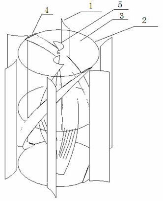
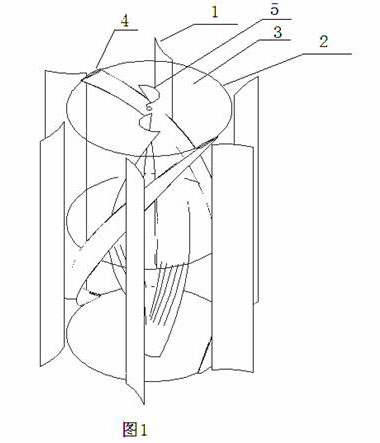
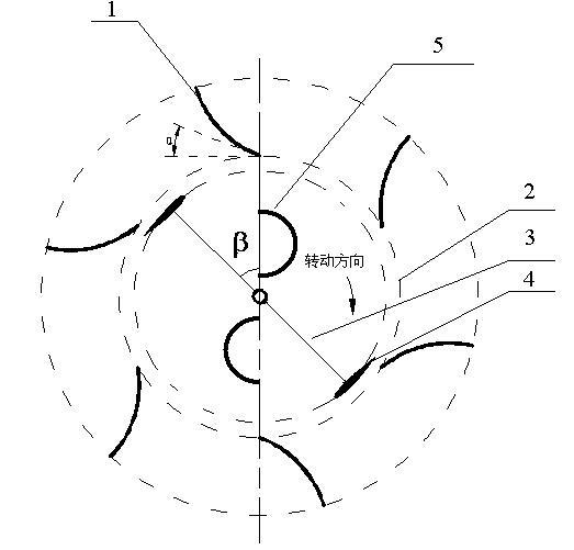
The invention relates to an energy-collecting speed-increasing reverse-rotating lift-drag composite type vertical shaft wind power machine which comprises an energy-collecting plate and a vertical shaft wind wheel, wherein the energy-collecting plate is a panel or an arc-shaped panel; the energy-collecting plate is installed at the periphery of the wind wheel; the distance between the energy-collecting plate and the outer diameter of the wind wheel is 0.0001-0.2 time of the diameter of the wind wheel; at the same time, the included angle alpha of the energy-collecting plate and the tangent line of the inscribed circle of the energy-collecting plate is 50 degrees-75 degrees; the vertical shaft wind wheel is provided with a 'twist type' lift-power type blade rotating reversely based on a dip angle and a 'twist type' resistance force type blade rotating reversely based on a certain dip angle; and a certain phase difference beta minus 45 degrees-45 degrees is formed between the lift-power type blade and the resistance force type blade. The wind power machine is suitable for the wind directions of any incoming flow direction, the flow speed can be improved greatly through contracting the flow channel, the energy consumption of the reverse side of the wind wheel can be reduced by a shield plate, and the high effective utilization of wind energy can be realized.
Description
Lift-drag composite vertical-axis wind turbine with energy-gathering speed-up and reverse-rotation technical field The invention relates to a wind-hydraulic machine, in particular to an energy-gathering speed-up-lift-drag composite counter-rotating vertical-axis wind machine suitable for any wind direction. technical background Wind energy is the fastest-growing clean energy among renewable energy sources, and it is also the most promising power generation method for large-scale development and commercialization. During the 10 years from 1993 to 2003, the annual growth rate of wind power generation in the world reached 29.7%. By the end of 2006, the global installed capacity of wind power reached 74.223 million kilowatts, and wind power generation accounted for 0.5% of the world's total electricity. Among them, the total installed capacity in Europe is 48.545 million kilowatts, accounting for 65.4% of the world's installed wind power capacity. In 2006, the cumulative ins...
Claims
Login to View More Application Information
Patent Timeline
 IPC IPC(8): F03D3/06F03D3/04
CPCY02E10/74
Inventor 黄典贵安启蒙
Owner SHANGHAI UNIV
Features
- R&D
- Intellectual Property
- Life Sciences
- Materials
- Tech Scout
- Unparalleled Data Quality
- Higher Quality Content
- 60% Fewer Hallucinations
Learn More Browse by: Latest US Patents, China's latest patents, Technical Efficacy Thesaurus, Application Domain, Technology Topic, Popular Technical Reports.
© 2025 PatSnap. All rights reserved.Legal|Privacy policy|Modern Slavery Act Transparency Statement|Sitemap|About US| Contact US: help@patsnap.com


