Gyration type hydraulic operated valve

A rotary valve technology, applied to valve details, valve devices, engine components, etc., can solve the problems of large overall height, small power and torque, burning motor, etc., and achieve high degree of automation control, large starting torque, Run Reliable Effects

Inactive Publication Date: 2008-07-02
徐学新
View PDF0 Cites 11 Cited by
  • Summary
  • Abstract
  • Description
  • Claims
  • Application Information

AI Technical Summary

Problems solved by technology

When the instantaneous torque required for opening the door is the largest, it is easy to cause the sum of the starting torque required for starting the fixed and stationary reducer plus the torque required for valve lifting, resulting in stuffy car accidents
When operating at a long distance, if it is not found in time, the motor will be burned
The biggest disadvantage of pneumatic valves is that the equipment and air source are bulky, the operating pressure is low, and the output power and torque are small, so the scope of application is limited.
The hydraulic valve refers to the valve driven by the oil cylinder. Due to the external dimensions of the oil cylinder and the original height of the valve, the overall height is too large, so it is not suitable for use in some occasions where the elevation is limited. In addition, this kind of valve cannot be used manually. on and off

Method used


Image

  • Gyration type hydraulic operated valve
  • Gyration type hydraulic operated valve
  • Gyration type hydraulic operated valve

Examples


Embodiment 1

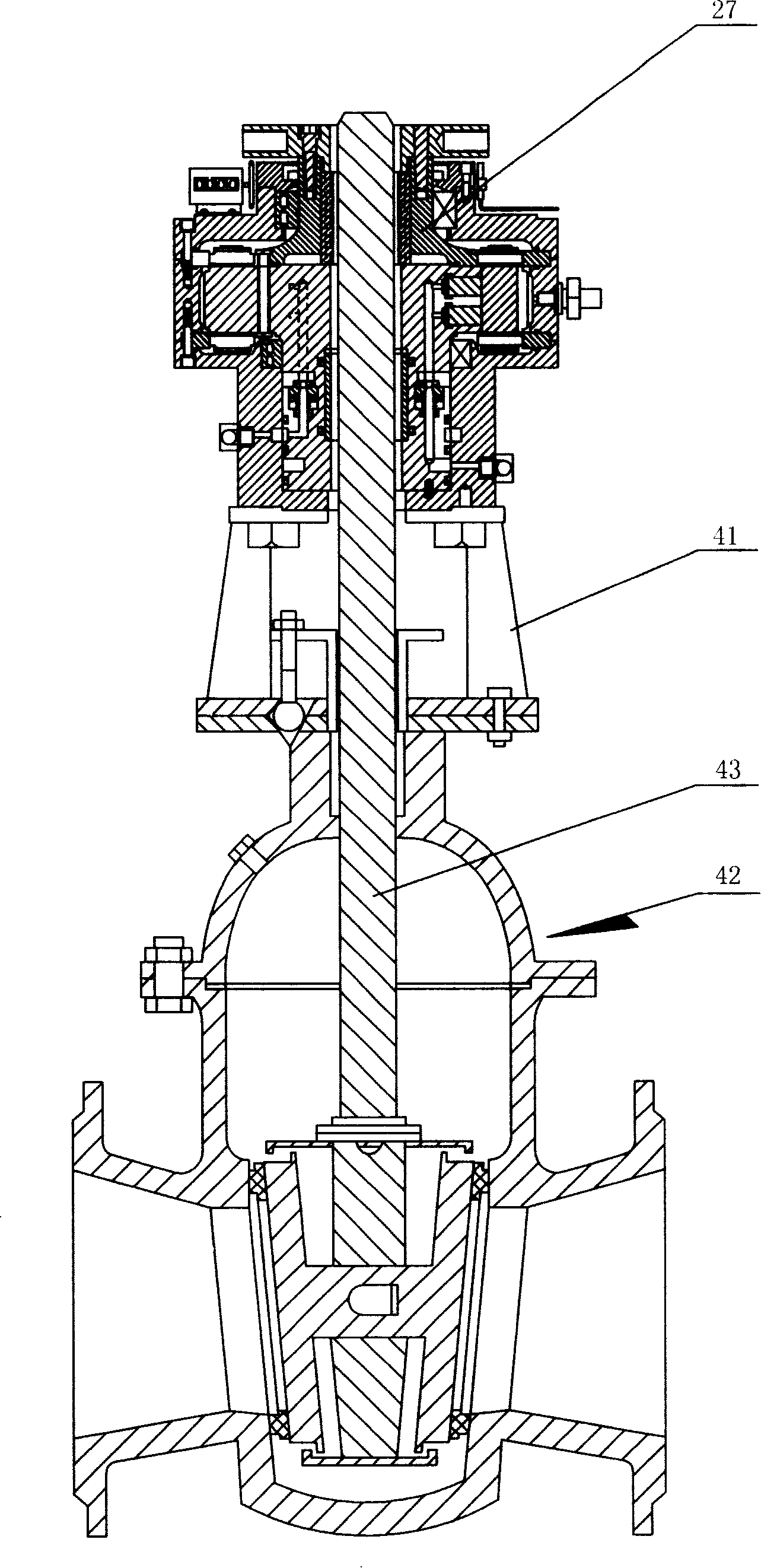
[0020] The rotary hydraulic valve includes a hydraulic motor, a valve 42 and a connecting bracket 41. The valve 42 is suitable for various known general purpose valves.

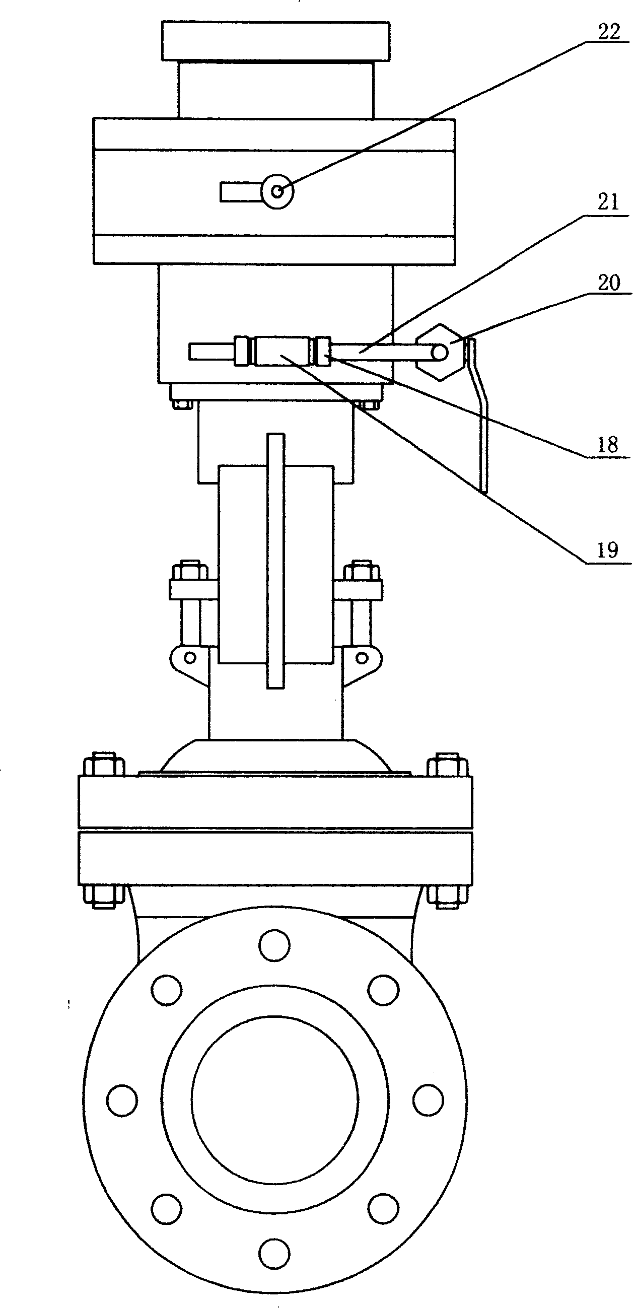
[0021] Hydraulic motor, including housing 1, front end cover 37, rear end cover 14, hollow output shaft 28, front flange 39, tapered roller bearing 34, tapered roller bearing 17, inner curved guide rail 4, beam 19, roller 21, Hollow plunger cylinder 2, a plurality of plungers 18, oil distribution sleeve 11, oil distribution plate 16, compression sleeve 15 and manual hinge plate 30 etc. A sealing member 3 and an inner curved guide rail 4 are respectively arranged in the track grooves at the upper and lower ends of the housing 1 . A plurality of plungers 18 are installed in the plunger holes on the hollow plunger cylinder body 2 respectively, and a crossbeam 19 is installed on the outer end of the plunger, and rollers 21 are respectively installed on the two ends of the crossbeam 19, and are held by the flat p...

Embodiment 2

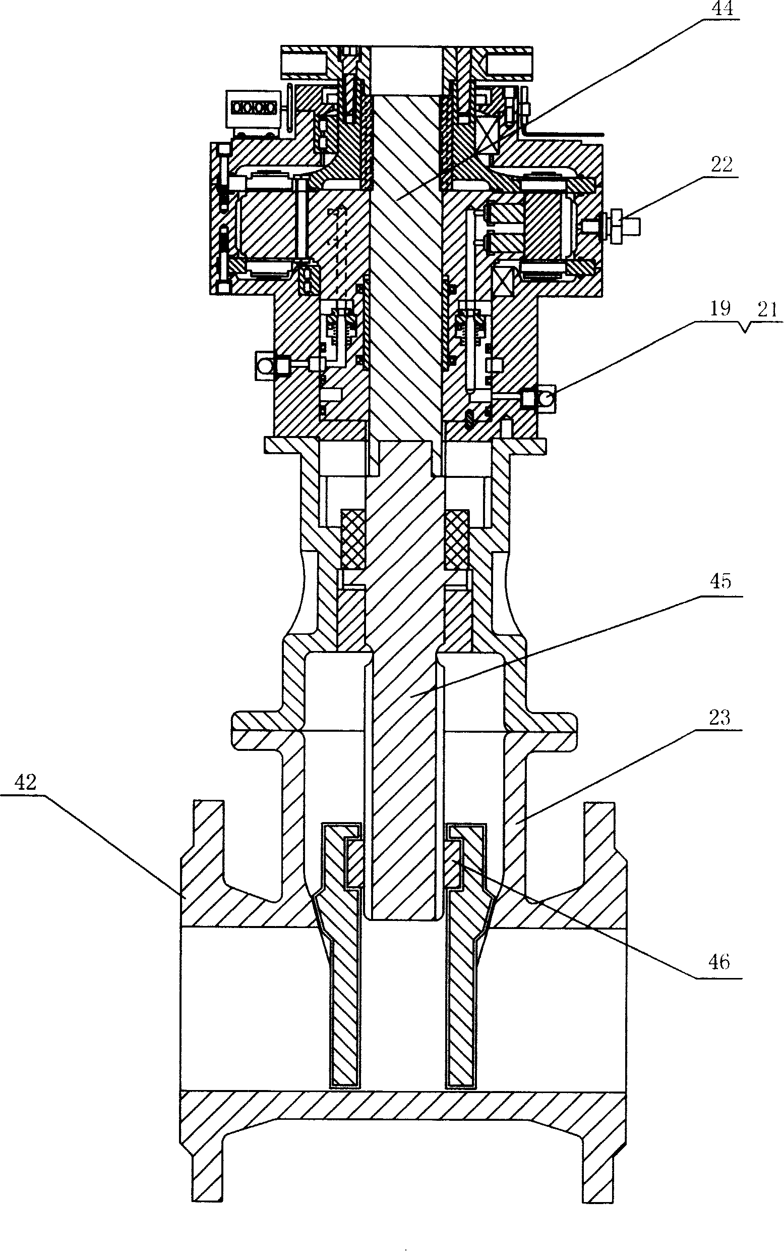
[0023] The second embodiment is basically the same as the first embodiment, except that the valve 42 is a dark rod valve structure, see image 3 , the valve stem does not move up and down. The valve stem 43 in the first embodiment is formed by connecting an upper solid valve stem 44 and a lower valve stem 45 , and the upper end of the upper solid valve stem 44 is connected with a key or a tooth in the inner hole of the hollow output shaft 28 . The driving nut 27 in the first embodiment is cancelled. The lower end of the lower valve rod 45 is connected with the nut 46 fixed on the valve plate with a T-shaped thread. Conforms to the connection method of the screw rod of the concealed rod valve.


PUM


Abstract

A rotary-type hydrodynamic valve is provided, which comprises a hydraulic motor, a valve and a supporter connecting the hydraulic motor with the valve. The top end of the valve rod of the valve is in thread connection with a driving screw which is arranged on the hollow output shaft of the hydraulic motor. When the hydraulic motor runs, the driving screw on the hollow output shaft can drive the valve rod to rotate and thus to move a valve plate up and down, thereby opening or closing the valve. The inventive rotary-type hydrodynamic valve has large starting torque; can change the driving torque along with the load change when opening or closing the valve; can set, display and control the opening or closing state of the valve; can ensure the valve to be opened or closed reliably and safely; can prolong the service life and reduce the noise; and can improve the automation degree and allow the manual operation.

Description

technical field [0001] The invention relates to a valve, in particular to a valve directly driven by a hydraulic motor. Background technique [0002] As liquid and gas medium conveying equipment, valves have been widely used in chemical industry, metallurgy, petroleum, mining, agriculture, municipal and other fields. In recent years, with the increasing demand for large-diameter and large-size valves, manual operation has become very difficult, even impossible. With the continuous improvement of the level of automation, a variety of valve drive methods have emerged, such as electric valves, pneumatic valves, hydraulic valves, etc. In practice, it is found that the above-mentioned valve driving method still has certain shortcomings and deficiencies. The torque and lifting force required for the opening and closing process of general valves are quite different in each stage. The biggest weakness of the electric valve is the small starting torque of the motor itself. When t...

Claims


Application Information

Patent Timeline
Patent Type & Authority Applications(China)
IPC IPC(8): F16K31/16F15B15/08
Inventor 徐学新
Owner 徐学新
Why Eureka
Try Eureka