Anti-leak oil feeding device
An oil supply device and anti-leakage technology, which is applied in fluid pressure actuation devices, fluid pressure actuation system components, mechanical equipment, etc., can solve the problem of limited hydraulic valves without anti-leakage measures, and achieve the effect of preventing leakage
Inactive Publication Date: 2011-06-15
陈伟明
View PDF5 Cites 0 Cited by
- Summary
- Abstract
- Description
- Claims
- Application Information
AI Technical Summary
Problems solved by technology
For the situation where leakage is occurring but the operator has not found it, there are no effective leakage prevention measures and limited hydraulic valves with leakage prevention function
Method used
View moreImage
Smart ImageViewing Examples

Examples
Embodiment Construction
Login to View More PUM
| Property | Measurement | Unit |
|---|---|---|
| Inner wall diameter | aaaaa | aaaaa |
Abstract
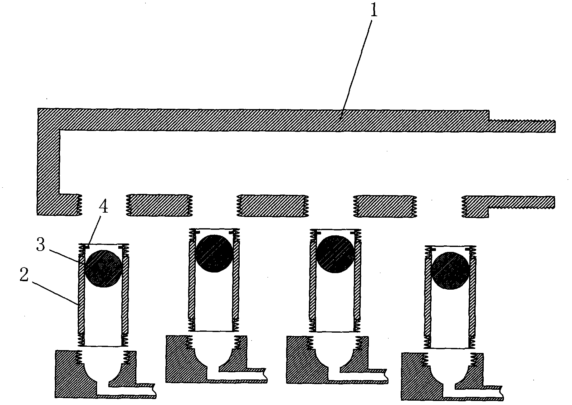
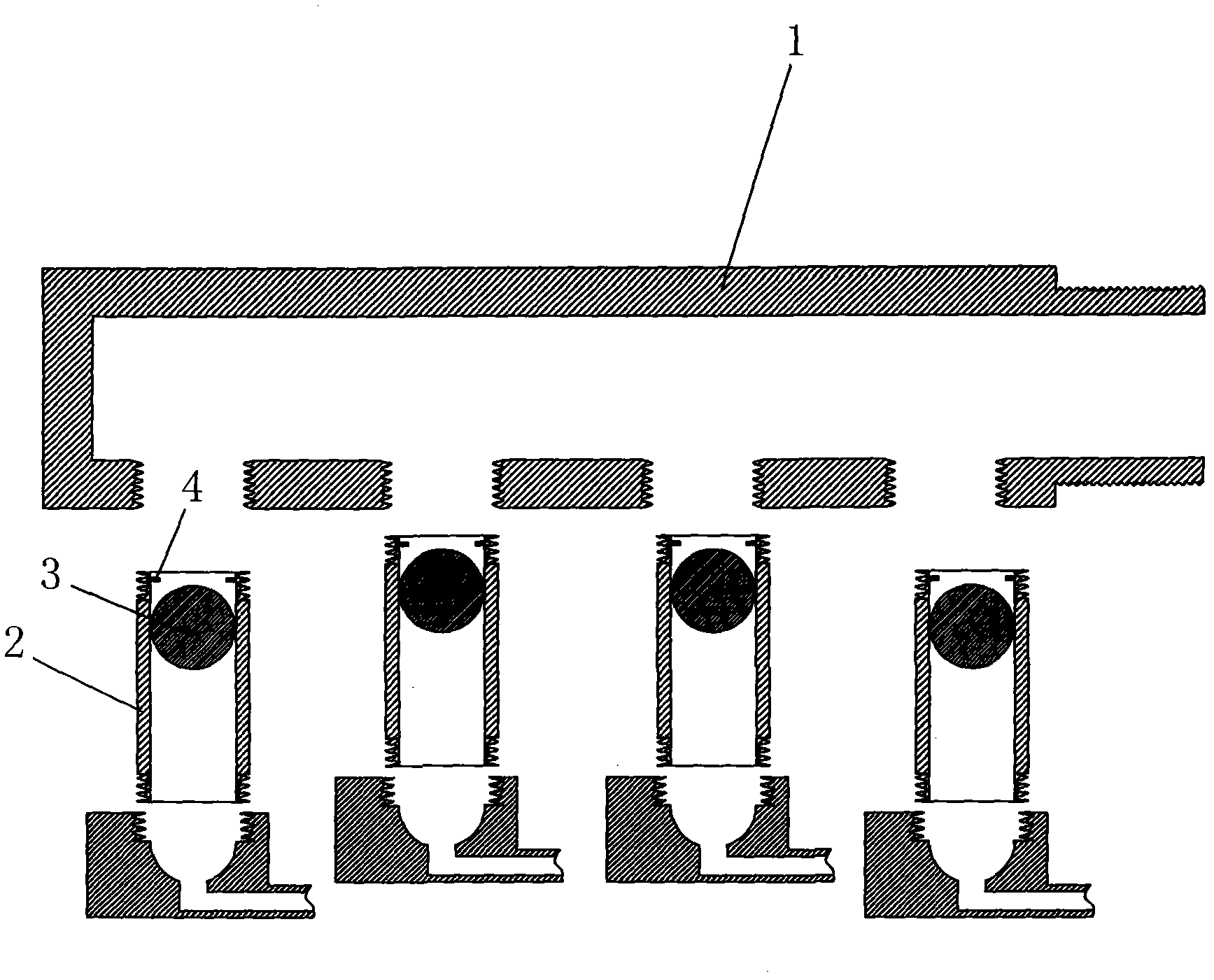
The invention discloses an anti-leak oil feeding device which comprises an oil-feeding pipeline and an oil expeller branch which is connected with the oil-feeding pipeline, wherein the oil-feeding pipeline is connected with an oil feeding tank; the oil expeller branch is connected with the oil-feeding pipeline through screw threads; the oil expeller branch is internally provided with a ball body and a baffle block; the ball body is made of materials the density of which is less than that of oil; and the diameter of the ball body is equal to the that of the inner wall of the oil expeller branch. The anti-leak oil feeding device provided by the invention has the beneficial effect that liquids can be automatically prevented from leaking out when leakage occurs.
Description
A leak-proof oil supply device technical field The invention relates to a leakage prevention device in a hydraulic system, in particular to a leakage prevention device applied to an oil supply pipeline. Background technique At present, although there are one-way throttle valves, stake valves and limited hydraulic valves in the hydraulic system, the one-way throttle valve can only achieve a single throttling function, and cannot automatically cut off the hydraulic circuit in the state of liquid leakage. Although the stake valve has the function of cutting off the hydraulic circuit, it cannot automatically cut off the hydraulic circuit and limit the volume of the pressurized liquid required during the movement of the execution system when the hydraulic circuit is in the state of pressurized liquid leakage. Prior to this, for the leakage of hydraulic system liquid, people generally adopted the method of using high-quality high-pressure resistant sealing rings and oil pipes, a...
Claims
Login to View More Application Information
Patent Timeline
 IPC IPC(8): F15B21/00
Inventor 陈伟明
Owner 陈伟明

PatSnap Eureka turns technology decisions into work you can execute. Powered by our Innovation Knowledge Graph, it runs expert workflows across engineering, life sciences, materials and intellectual property. Get your review-ready output in minutes.


