Shaft spring of railway vehicle

A railway vehicle and shaft spring technology, which is applied in the field of railway vehicle shaft springs, can solve problems such as torsional deformation, impact, easy deterioration of durability, etc., and achieve the effects of reducing elastic force weakening, improving durability, and improving durability

Active Publication Date: 2011-06-15
NITTA CHEM IND PROD CO LTD
View PDF6 Cites 4 Cited by
  • Summary
  • Abstract
  • Description
  • Claims
  • Application Information

AI Technical Summary

Problems solved by technology

[0004] However, when a torsional force acts on the shaft spring due to the passage of a curve, etc., the outer rubber layer whose horizontal dimension is longer than the vertical dimension is subjected to a large torsional force and is torsionally deformed, and its frequency also increased
That is, in a general design based on the upper and lower loads that have the greatest impact on ride comfort, the outer rubber layer has a greater burden as a whole and tends to deteriorate (poor durability). The short life of the shaft spring becomes a problem such as the life of the shaft spring
[0005] In this way, it is considered that the upper and lower dimensions of the outer rubber layer should be set larger than the existing technology to ensure the capacity against torsion, but in this case, the spring constant relative to the upper and lower loads becomes larger, which brings bad ride comfort. impact, so it is difficult to achieve
Therefore, there is room for improvement in realizing an axle spring having both good riding comfort and long life

Method used


Image

  • Shaft spring of railway vehicle
  • Shaft spring of railway vehicle
  • Shaft spring of railway vehicle

Examples


Embodiment 1

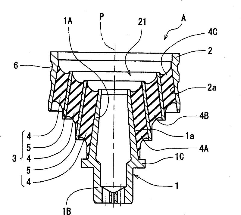
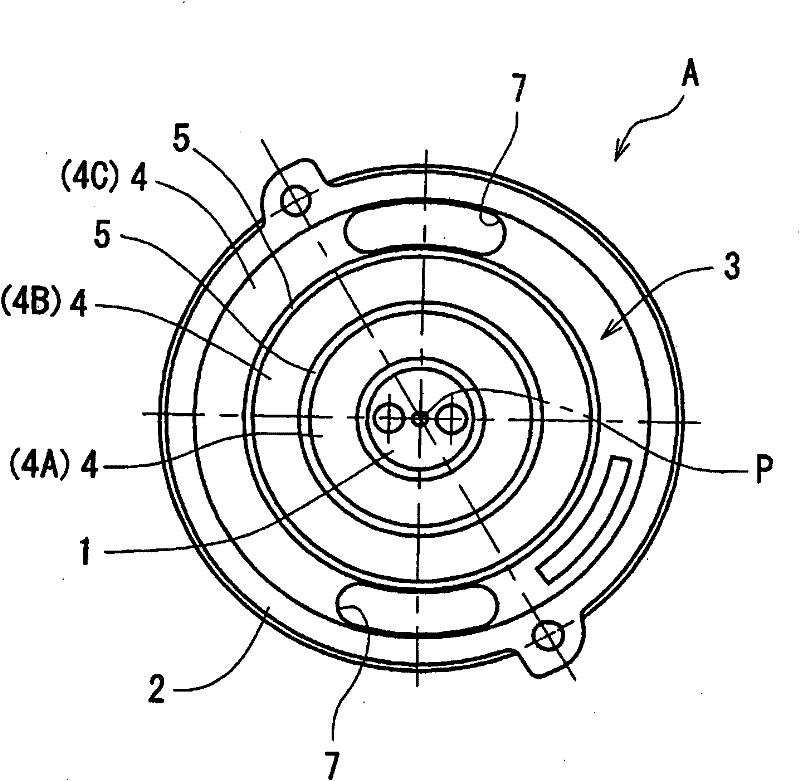
[0024] Such as figure 1 , figure 2 As shown, the railway vehicle axle spring A is configured to have: a main shaft 1, an outer cylinder 2 having the same (or substantially the same) longitudinal axis P as the main shaft 1, and formed to be concentric (or substantially concentric) with the longitudinal axis P. ) in the state of radially inwardly and outwardly laminating the laminated rubber structure of three layers of rubber layers 4 and two layers of hard partition walls (metal rings) 5, and the elastic part 3 sandwiched between the main shaft 1 and the outer cylinder 2. In the case where the radially inner and outer elastic portions 3 adopt a laminated rubber structure, the number of hard partition walls 5 is a value obtained by subtracting one from the number of rubber layers 4 .

[0025] The main shaft 1 is made of metal, and has a conical cylindrical shaft upper part 1A with an enlarged lower part, a cylindrical lower shaft part 1B with a solid circular cross-section wi...


PUM


Abstract

The invention provides a shaft spring of a railway vehicle which is improved through research and development, will not trigger the deterioration of riding comfortableness, and can improve endurance. An elastic part (3) of a lamination rubber structure is clamped between a main shaft (1) and an outer cylinder (2) having an axle center (P) equal or approximately equal to the main shaft, forming the shaft spring for the railway vehicle. The elastic part (3) is alternately laminated with a plurality of rubber layers (4A, 4B, 4C) and one or over one hard bulkheads (5) in internal and external radial directions under the state that the elastic part (3) is or is approximately concentric to the axle center (P). In the plurality of rubber layers (4A, 4B, 4C), an external side rubber layer (4C) is made from rubber materials with high spring constant, a middle rubber layer (4B) is made from rubber materials of moderate spring constant, and an internal side rubber layer (4A) is made from rubber materials of low spring constant.

Description

technical field [0001] The present invention relates to an axle spring for railway vehicles, which is composed of an elastic part of a laminated rubber structure interposed between a main shaft and an outer cylinder having the same or substantially the same axial center as the main shaft, and the elastic part is aligned with the axial center. A plurality of rubber layers and one or more hard partition walls are alternately laminated in the radially inner and outer directions in a concentric or substantially concentric state. Background technique [0002] As a prior art example of such an axle spring for railway vehicles, a laminated rubber structure using a straight cylinder as shown in Patent Document 1, or a structure with a cross-sectional shape inclined in a figure-eight shape as shown in Patent Document 2 is known. Laminated rubber structure (shaft spring known as a so-called "cone brake"). Axle springs for railway vehicles are being popularized instead of conventional...

Claims


Application Information

Patent Timeline
Patent Type & Authority Applications(China)
IPC IPC(8): F16F9/05
Inventor 松浦宏佳浜田晃
Owner NITTA CHEM IND PROD CO LTD
Why Eureka
Try Eureka