

Snail-like centrifugal ventilation device
A ventilation device and snail technology, which are applied in ventilation systems, space heating and ventilation, separation methods, etc., can solve the problems that the wind speed cannot be too high, restrict the wind speed, and affect the work efficiency of the system, so as to improve work efficiency and improve ventilation. Amount, easy to use effect
Inactive Publication Date: 2011-06-15
ZHUHAI FEIPENG PURIFICATION TECH
View PDF6 Cites 7 Cited by
- Summary
- Abstract
- Description
- Claims
- Application Information
AI Technical Summary
Problems solved by technology
At present, when the air purification system adjusts the air temperature, the condenser will produce water droplets, which will affect the working efficiency of the system. To improve the efficiency, ventilation needs to be designed. The ventilation speed of traditional air purification equipment cannot exceed 25 m / s, and the wind speed is too high The phenomenon of "flying water" will occur, that is, tiny water droplets fly to other components with the high-speed wind, affecting the work of other components, or in the high-voltage electrostatic precipitator system, it is necessary to use water spray to remove dust, and the wind speed cannot exceed High, the airflow passing through the dust removal channel is also easy to bring water droplets to other components. This "flying water" phenomenon seriously restricts the increase of wind speed, affects the working efficiency of the system and the air purification effect, and causes some inconvenience to users.
Method used
View moreImage
Smart ImageViewing Examples

Examples
Embodiment 1
Embodiment 2
Embodiment 3
Login to View More PUM
 Abstract
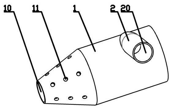
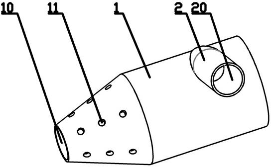
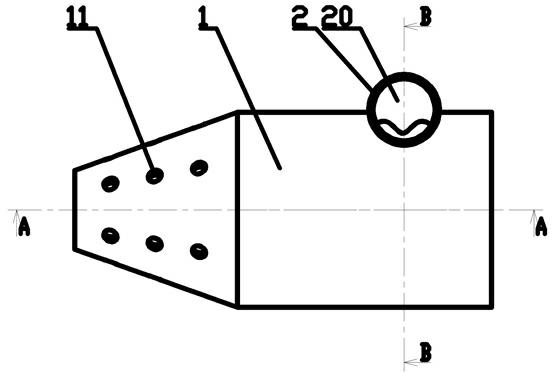
The invention discloses a snail-like centrifugal ventilation device, and aims to provide the snail-like centrifugal ventilation device which can improve the ventilation volume of an air purification system and the working efficiency of the system. The snail-like centrifugal ventilation device comprises a main ventilation pipe (1) and an air inducing pipe (2), wherein the front half part of the main ventilation pipe (1) is circular, and the rear half part of the main ventilation pipe (1) is a reducing conical part; a port of the front half part of the main ventilation pipe (1) is sealed, and the port of the rear half part of the main ventilation pipe (1) is an air outlet (10); the side wall of the rear half part of the main ventilation pipe (1) is provided with a plurality of small holes (11); and the air inducing pipe (2) is communicated with the front half part of the main ventilation pipe (1), is perpendicular to the main ventilation pipe (1) and is tangent to the main ventilation pipe (1). The ventilation device can be widely applied to purification systems.
Description
A spiral centrifugal ventilation device technical field The invention relates to a spiral centrifugal ventilation device. Background technique At present, when the air purification system adjusts the air temperature, the condenser will produce water droplets, which will affect the working efficiency of the system. To improve the efficiency, ventilation needs to be designed. The ventilation speed of traditional air purification equipment cannot exceed 25 m / s, and the wind speed is too high The phenomenon of "flying water" will occur, that is, tiny water droplets fly to other components with the high-speed wind, affecting the work of other components, or in the high-voltage electrostatic precipitator system, it is necessary to use water spray to remove dust, and the wind speed cannot exceed High, the airflow passing through the dust removal channel is also easy to bring water droplets to other components. This "flying water" phenomenon seriously restricts the increase of win...
Claims
Login to View More Application Information
Patent Timeline
 IPC IPC(8): B01D45/16F24F7/04B01D5/00
Inventor王浦林
OwnerZHUHAI FEIPENG PURIFICATION TECH