
Method and device for verifying high-accuracy direct-current comparator

A direct current, high-accuracy technology, applied in the field of electrical measurement, can solve problems such as high cost, cumbersome verification process and data processing, and inability to directly verify 1:1 ratio errors, so as to overcome errors, achieve uniform and symmetrical electrical performance, and avoid Effect of Lead Resistance Interference

Active Publication Date: 2013-09-25
BEIJING DONGFANG MEASUREMENT & TEST INST
View PDF6 Cites 0 Cited by
  • Summary
  • Abstract
  • Description
  • Claims
  • Application Information

AI Technical Summary

Problems solved by technology

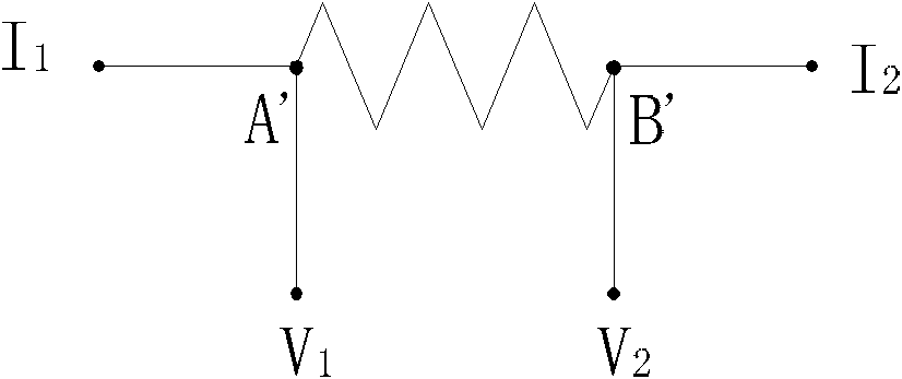
The relationship deduced above all assumes that in an ideal situation, the resistance of the connection point is zero. In actual situations, the resistance of the resistance connected to the lead wire of the terminal button and the resistance of the parallel connection will directly affect the resistance of the invented device. measurement results, so the formulas derived above cannot be directly used in practice, and special design is required to take effective measures to improve
[0027] 3. Cannot directly verify the 1:1 ratio error
[0028] For high accuracy (accuracy up to 10 -7 -10 -8 order of magnitude) for the verification of DC current comparators. At present, there is no verification device dedicated to calibrating the proportional error of such instruments in China. However, foreign countries use low-temperature current comparator verification devices for verification. The cost of this device is very high, and the verification process and Data processing is quite cumbersome

Method used


Image

  • Method and device for verifying high-accuracy direct-current comparator
  • Method and device for verifying high-accuracy direct-current comparator
  • Method and device for verifying high-accuracy direct-current comparator

Examples


Embodiment Construction

[0054] The present invention will be described below in conjunction with the accompanying drawings.

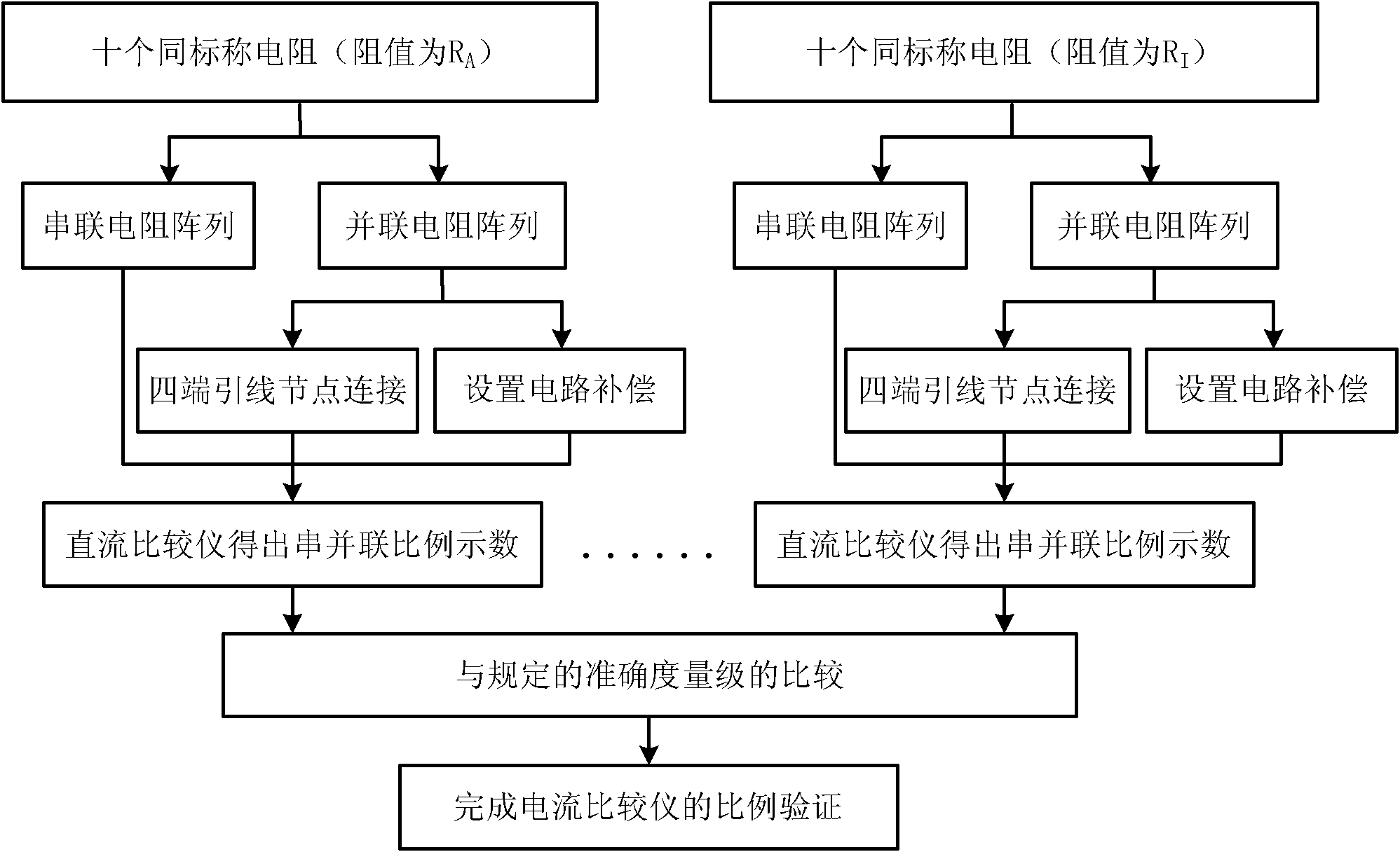
[0055] figure 2 It is a flow chart of the verification method of the high-accuracy DC current comparator for resistance measurement of the present invention. First connect ten resistors with the same nominal value (resistance value is R A ) are connected in series and parallel to form a series resistance array and a parallel resistance array respectively. The parallel resistance array uses a four-terminal lead node structure to connect the nodes at both ends of each parallel resistance, and when the resistance arrays are connected in parallel, the external short circuit is used to set the short circuit compensation, and then through the DC The current comparator is used for proportional measurement, and the DC current comparator can obtain the series-parallel proportional display respectively; three or more groups of resistors are connected in series and parallel, and then t...


PUM


Abstract

The invention provides a method and device for verifying a high-accuracy direct-current comparator for resistance measurement. The method comprises the following steps: firstly connecting two or more than two same nominal resistors in serial and in parallel so as to respectively form serial resistor arrays and parallel resistor arrays; connecting the parallel resistor arrays with nodes at the two ends of all parallel resistors by virtue of a four-end lead node structure, and setting short-circuit compensation for externally-connected short-circuit sheets when the resistor arrays are connected in parallel; then carrying out proportion measurement by virtue of measured direct-current comparators, and obtaining serial-parallel proportion readings by the direct-current comparators; connecting three groups or more than three groups of nominal resistors in series and in parallel, and then carrying out the proportion measurement by virtue of the measured direct-current comparators; and comparing with the specified accuracy level according to the production of the serial-parallel proportion readings of all the groups of serial and parallel resistor arrays, so as to realize the proportion verification of the direct-current comparators. By utilizing the method provided by the invention, accurate verification of proportional errors of the high-accuracy (the accuracy reaches 10-7-10-8 levels) direct-current comparator used for resistance measurement can be realized.

Description

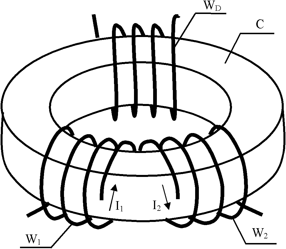
technical field [0001] The invention relates to an electrical measurement technology, in particular to a verification method and device for a high-accuracy DC current comparator for resistance measurement. Background technique [0002] The emergence of the current comparator is an important milestone in modern electrical measurement, which has successively solved the problems of high-accuracy measurement of voltage, current, resistance and power energy. With the rapid development of electronic technology, servo power supplies with excellent performance and sensitive magnetic flux detectors have been developed one after another, as well as the emergence of materials with high magnetic permeability. -8 An order of magnitude of current comparators creates the necessary conditions. [0003] The DC current comparator is composed of an iron core and a coil. For a DC current comparator, its structure diagram is as follows: figure 1 As shown, on a ring-shaped high-permeability iro...

Claims


Application Information

Patent Timeline
Patent Type & Authority Patents(China)
IPC IPC(8): G01R35/00
Inventor 蔡建臻黄晓钉李继东
Owner BEIJING DONGFANG MEASUREMENT & TEST INST
Learn More