

Rotating driving force receiver and drive component
A technology for driving components and receiving heads, which is applied in the fields of electrography, optics, instruments, etc., can solve problems such as jamming, and achieve the effect of avoiding jamming, simple assembly and stable operation.
Active Publication Date: 2011-06-15
PRINT RITE UNICORN IMAGE PROD CO LTD
View PDF7 Cites 19 Cited by
- Summary
- Abstract
- Description
- Claims
- Application Information
AI Technical Summary
Problems solved by technology
When the process cartridge is dropped or taken out, the problem of jamming easily occurs between the rotary drive force receiving head in the above-mentioned photosensitive drum drive assembly and the drive part of the imaging device
Therefore, the above-mentioned photosensitive drum driving assembly still has room for further improvement
Method used
View moreImage
Smart ImageViewing Examples

Examples
Embodiment Construction
Login to View More PUM
 Abstract
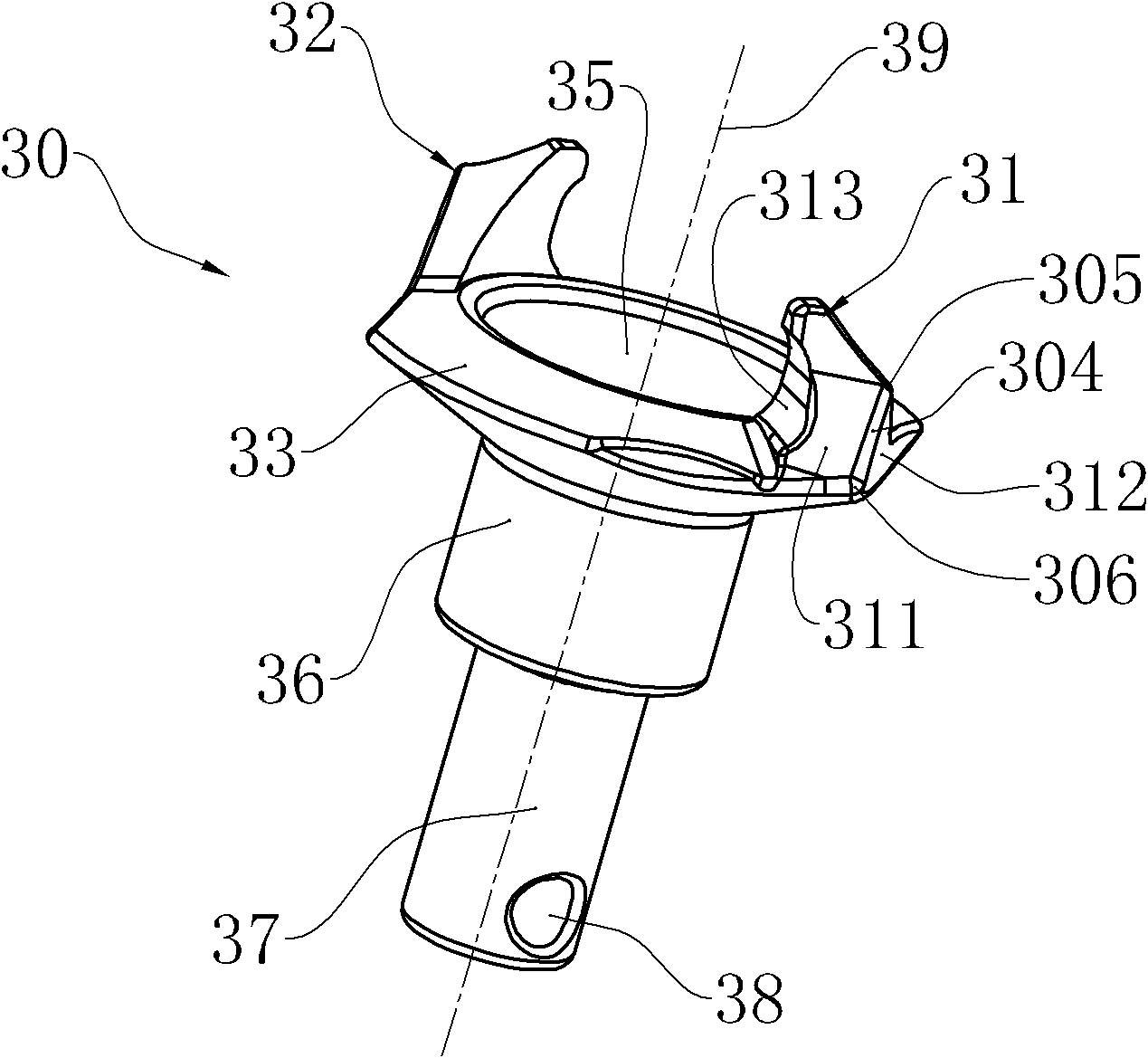
The invention relates to a rotating driving force receiver and a drive component. The receiver is provided with an inwards concave spherical surface, an approaching surface positioned on the periphery of the spherical surface, and a first convex pawl and a second convex pawl extended outwards, wherein the surfaces of each of the convex pawls are both provided with an occlusal surface matched with an imaging equipment drive component and two side surfaces which are used for guiding and are transited smoothly; the two side surfaces are abutted through a transition edge which is inclined relative to the direction of an axial line; the transition edge is provided with a first endpoint and a second endpoint; the second endpoint is positioned on the second surface; a first bottom line and a second bottom line are crossed at the second endpoint; the second endpoint is a point, farthest from the axial line, on a convex pawl; and the first endpoint is closer to the axial line than the second endpoint. The rotating driving force receiver and the drive component can reduce a dead point position area when a machine falls or a processing cartridge is taken out to the maximum and avoid a locking problem between the rotating driving force receiver and the imaging equipment drive component, so that a photosensitive drum can be driven to work safely and reliably.
Description
Rotary drive receiver and drive assembly technical field The present invention relates to a rotary driving force receiving head and a drive assembly having the rotary driving force receiving head. Background technique Electrophotographic image forming apparatuses include copiers, laser printers, and the like. An electrophotographic image forming apparatus generally has a process cartridge in it, and the process cartridge can be attached to and detached from the main assembly of the electrophotographic image forming apparatus. For example, a process cartridge prepared by integrally assembling a photosensitive drum, and at least one of developing means, charging means and cleaning means as process means into a cartridge body. Existing process cartridges include the following types: a first process cartridge prepared by integrally assembling a photosensitive drum and a developing device, a charging device, and a cleaning device in a cartridge; and a second process cartridg...
Claims
Login to View More Application Information
Patent Timeline
 IPC IPC(8): G03G15/00G03G21/18
CPCG03G15/757G03G21/186
Inventor汤付根周宏辉
OwnerPRINT RITE UNICORN IMAGE PROD CO LTD