

Radio frequency coaxial connector
A radio frequency coaxial and connector technology, applied in the direction of connection, two-part connection device, device for joining/disconnecting connection parts, etc., can solve the problems of connectors not fitting in place, failure, signal transmission efficiency reduction, etc., to achieve cooperation Reliable, Simple Effects
Inactive Publication Date: 2011-06-15
SHANGHAI AEROSPACE SCI & IND ELECTRIC APPLIANCE RES INST
View PDF4 Cites 12 Cited by
- Summary
- Abstract
- Description
- Claims
- Application Information
AI Technical Summary
Problems solved by technology
Because the radio frequency coaxial connectors in the prior art do not have the function of rotating and adjusting in any direction, in the case of strong vibration, the plug and socket will cause mechanical damage under the action of external force, resulting in improper fit of the connector and poor signal transmission. Reduced efficiency or even complete failure
Method used
View moreImage
Smart ImageViewing Examples

Examples
Embodiment Construction
Login to View More PUM
 Abstract
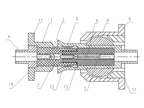
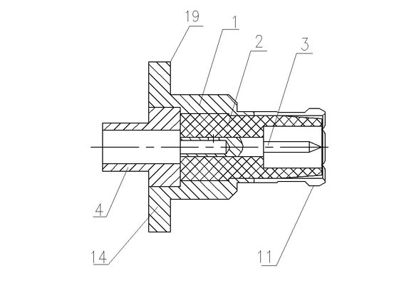
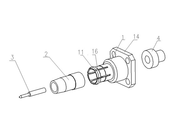
The invention discloses a radio frequency coaxial connector, which comprises a plug and a socket, wherein the plug is formed by sleeving an A outer conductor, an A insulator and an A inner conductor and the socket is formed by sleeving a B outer conductor, a B insulator and a B inner conductor. The radio frequency coaxial connection is characterized in that: the A conductor is a sleeve provided with a flange at one end and a convex ring bayonet at the other end, wherein a cable connector is sleeved in the flange of the A outer conductor; the B outer conductor is a sleeve, wherein a bell mouth is arranged at one end of the B outer conductor, and a ball body is clamped at the middle part of the B outer conductor and is sleeved on a spherical support; and the plug is connected with the socket to realize radio frequency coaxial connection. Compared with the prior art, the radio frequency coaxial connector has the advantages of simple structure and reliable cooperation, and is particularly suitable for transmitting high-frequency signals in a strong vibration environment; moreover, the good and stable radio frequency performance and the reliable connection of the coaxial connector under a vibration environment are ensured.
Description
RF coaxial connector technical field The invention relates to the technical field of electric component plugging, in particular to a radio frequency coaxial connector suitable for a new type of interface. Background technique RF coaxial connectors are used for interconnection between circuit boards, RF modules and RF modules, and circuit boards and RF modules. In today's electronic communication field, such as voice, data and image transmission, the required signal transmission speed is getting faster and faster, and the stability and reliability are getting higher and higher. However, some equipment is often used in harsh environments, such as mountain driving vehicles, ground drilling equipment and high-altitude aircraft, etc., and must ensure the reliability and stability of high-frequency signal transmission while being subjected to strong vibrations. Because the radio frequency coaxial connectors in the prior art do not have the function of rotating and adjusting in...
Claims
Login to View More Application Information
Patent Timeline
 Patent Type & AuthorityApplications(China)
IPC IPC(8): H01R24/40H01R13/62
Inventor陈刚
OwnerSHANGHAI AEROSPACE SCI & IND ELECTRIC APPLIANCE RES INST