Method and system for sampling high-frequency periodic signals

A periodic signal and sampling system technology, applied in signal transmission systems, electrical signal transmission systems, instruments, etc., can solve problems such as poor precision, complex hardware circuits, and difficult debugging, and achieve high reliability, simple hardware circuits, and sampling accuracy Controllable Effects

Active Publication Date: 2013-09-04
东莞市同门电子科技有限公司
View PDF1 Cites 0 Cited by
  • Summary
  • Abstract
  • Description
  • Claims
  • Application Information

AI Technical Summary

Problems solved by technology

The hardware circuits of these methods are complex, difficult to debug, and poor in accuracy. Many instruments use this type of method, which has equivalent functions in name, but cannot measure and recover high-frequency signals.

Method used


Image

  • Method and system for sampling high-frequency periodic signals
  • Method and system for sampling high-frequency periodic signals
  • Method and system for sampling high-frequency periodic signals

Examples


Embodiment Construction

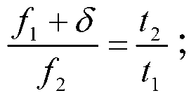
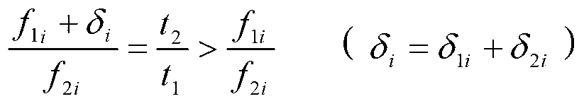
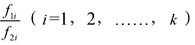
[0038] Embodiments of the present invention will now be described with reference to the drawings, in which like reference numerals represent like elements. As mentioned above, the present invention provides a sampling method and system for high-frequency periodic signals, which can effectively sample and recover high-frequency periodic signals, and have high sampling accuracy and strong controllability.

[0039] First please refer to Figure 1~3 , shows the specific constituent modules of the high-frequency periodic signal sampling system of the present invention. Such as figure 1As shown, the sampling system of the high-frequency periodic signal of the present invention includes a signal conditioning unit 10, a sampling unit 20, a frequency counting unit 30, a data processing unit 40 and a display unit 50, and the signal conditioning unit 10 is used to convert the input signal and the sampling signal Perform level comparison and signal conditioning such as automatic gain ad...


PUM


Abstract

The invention discloses a method for sampling high-frequency periodic signals, comprising the following steps: sampling input signals by using sampling signals, and storing data of the sampled input signals; counting frequencies of the input signals and the sampling signals so as to obtain frequency ratio of the input signals to the sampling signals; processing the data of the stored sampled input signals by using the frequency ratio of the input signals to the sampling signals so as to restore the input signals; and outputting the recovered input signals so as to display waveforms. By utilizing the method for sampling the high-frequency periodic signals provided by the invention, the high-frequency periodic signals can be effectively sampled and recovered by using low speed analog / digital, and the method is high in sampling precision and strong in controllability. The invention further discloses a system for sampling high-frequency periodic signals.

Description

technical field [0001] The present invention relates to sampling technology, more specifically to a sampling method and system for high-frequency periodic signals. Background technique [0002] The data processing speed of modern electronic information technology is getting faster and faster. For devices such as computers, mobile phones, mobile TVs, GPS navigation, RFID non-stop charging, etc., the communication frequency has reached the order of G. The development and manufacture of these products are inseparable from high-frequency Digital oscilloscopes, they are the eyes of developers. [0003] In a digital oscilloscope, an analog-to-digital conversion (A / D) is first performed on the input signal, and the analog signal is converted into a digital signal, and then processed and displayed. The speed of the A / D converter determines the sampling rate of the instrument, and also determines the maximum operating frequency index of the instrument, that is, the upper limit of th...

Claims


Application Information

Patent Timeline
Patent Type & Authority Patents(China)
IPC IPC(8): H03M1/54
Inventor 余成曹亚斌赖树明黄光标李强
Owner 东莞市同门电子科技有限公司
Why Eureka
Try Eureka