Dual-power dual-fan integrated switch with preferred main power

A technology of main power supply and dual power supply, which is applied in the direction of electric switch, ventilation of mine/tunnel, circuit, etc., and can solve problems such as wind stop and continuity of air supply can no longer be guaranteed.

Inactive Publication Date: 2011-06-22
山西潞安石圪节煤业有限责任公司 +1
View PDF5 Cites 8 Cited by
  • Summary
  • Abstract
  • Description
  • Claims
  • Application Information

AI Technical Summary

Problems solved by technology

[0002] In order to ensure the safety of air supply to the coal mine excavation face, the "Coal Mine Safety Regulations" requires that the underground excavation face must be equipped with two sets of power supplies and two sets of fans, one of which is working and the other is standby, and requires automatic switching of dual fans and dual power supplies; At present, the automatic switching control technology of dual power supply and double fan has been reported in the literature, for example, the development of automatic switching device for local ventilators in mines published by Dong Dai'an in Mining Safety and Environmental Protection Magazine in June 2005, Chen Chaofan in December 2001 in Coal Mine Safety Magazine The

Method used


Image

  • Dual-power dual-fan integrated switch with preferred main power
  • Dual-power dual-fan integrated switch with preferred main power
  • Dual-power dual-fan integrated switch with preferred main power

Examples


Embodiment 1

[0055] The automatic setting is used as follows:

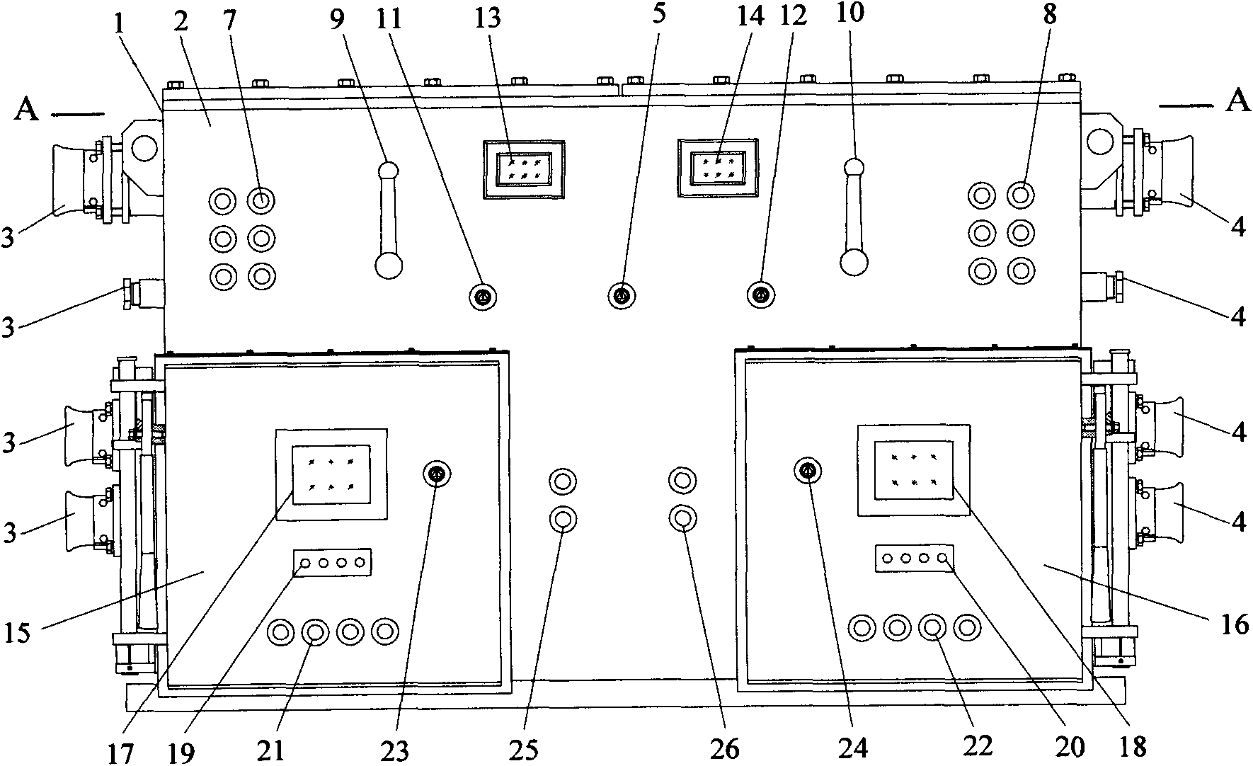
[0056] ①The switch box, the first and second control parts on the front panel, the circuit board circuit, and the controlled fan are all in the quasi-working state, and the charging indicators A11 and A21 are on;

[0057] ②Place the selector switch in the automatic position;

[0058] ③ Turn on the first and second power switches in turn, the control circuit obtains power from the transformer TR11, and the transformer TR12 is powered to enter the standby state;

[0059] ④Press the start button SB10 in the button 7 of the first power supply layer, the vacuum circuit breaker QF11 is closed, and the charging indicator A12 is turned on;

[0060] ⑤Press the start buttons SB11 and SB12 in the button 7 of the first power layer, the vacuum contactors KM11 and KM12 are pulled in, and the charging indicators A13 and A4 are turned on;

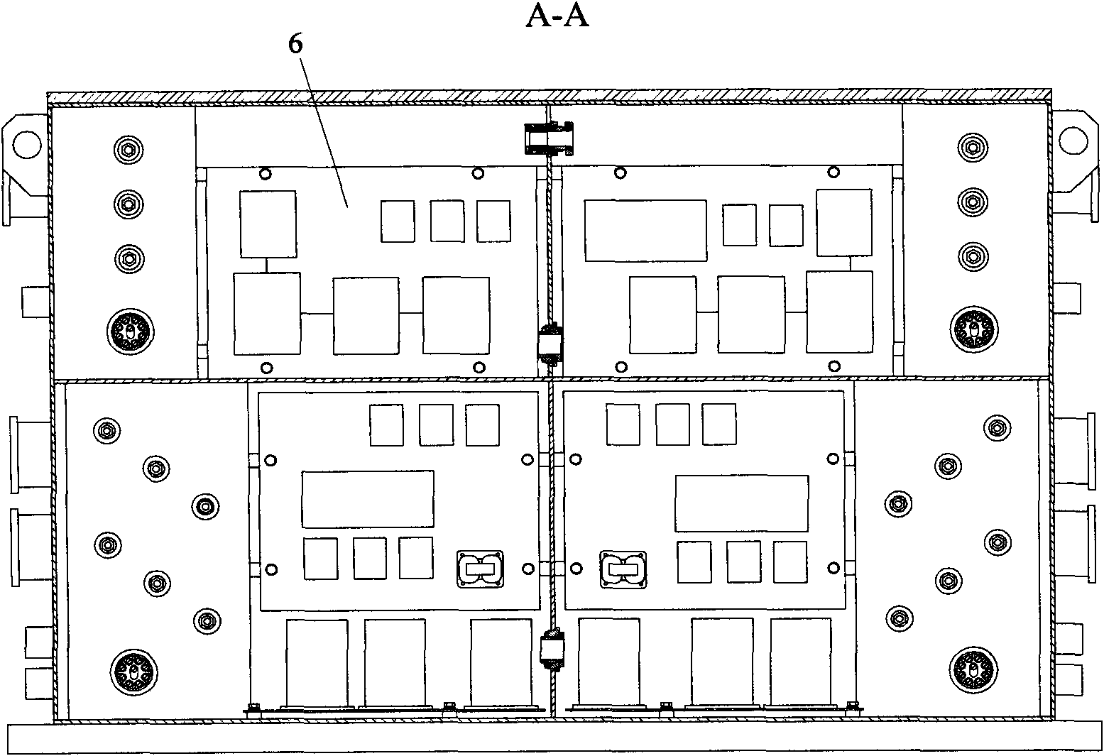
[0061] ⑥Close the first isolating switch 9, the control circuit in the first control box starts to wo...

Embodiment 2

[0073] Manual settings are used as follows:

[0074] ①The switch box, the first and second control parts on the front panel, the circuit board circuit, and the controlled fan are all in the quasi-working state, and the charging indicators A11 and A21 are on;

[0075] ②Place the selector switch in the manual position;

[0076] ③ Turn on the first and second power switches in turn, the control circuit obtains power from the transformer TR11, and the transformer TR12 is powered to enter the standby state;

[0077] ④Press the start button SB10 in the button 7 of the first power supply layer, the vacuum circuit breaker QF11 is closed, and the charging indicator A12 is turned on;

[0078] ⑤Press the start buttons SB11 and SB12 in the button 7 of the first power layer, the vacuum contactors KM11 and KM12 are pulled in, and the charging indicators A13 and A4 are turned on;

[0079] ⑥Close the first isolating switch 9, the control circuit in the first control box is electrified and s...


PUM


Abstract

The invention relates to a dual-power dual-fan integrated switch with a preferred main power. The dual-power dual-fan integrated switch mainly comprises a switch box, a front panel, an indicator light, a power layer button, a disconnecting switch, a power switch, a selective switch, a control box, a display screen, a setting button, a fan switch, a function selection button, a main switch, a junction box, a circuit board, and a wire; the dual-power dual-fan integrated switch is provided with two fans, two control box panels and two control circuits; the control circuits are controlled by a main circuit, a stand-by circuit and a microcomputer program, automatic conversion can be performed between the fans, the main power supply is automatically prioritized, and quick conversion and instantaneous automation are realized. The dual-power dual-fan integrated switch has an advanced design, is reasonable in setting, safe, stable and reliable and is a very ideal automatic control switching device for a coal mine underground fan.

Description

technical field [0001] The invention relates to an integrated switch with dual power sources and double fans with priority on the main power source, and belongs to the technical field of control and application of underground electrical equipment in coal mines. technical background [0002] In order to ensure the safety of air supply to the coal mine excavation face, the "Coal Mine Safety Regulations" requires that the underground excavation face must be equipped with two sets of power supplies and two sets of fans, one of which is working and the other is standby, and requires automatic switching of dual fans and dual power supplies; At present, the automatic switching control technology of dual power supply and double fan has been reported in the literature, for example, the development of automatic switching device for local ventilators in mines published by Dong Dai'an in Mining Safety and Environmental Protection Magazine in June 2005, Chen Chaofan in December 2001 in Co...

Claims


Application Information

Patent Timeline
IPC IPC(8): E21F17/06E21F1/00H01H9/02
Inventor 杨毅杨同敏呼世杰王迁李安平李永红姚孝平王刚张来柱张星荣孟润泉
Owner 山西潞安石圪节煤业有限责任公司
Why Eureka
Try Eureka