Wind driven generator speed limiting device

A technology for wind turbines and speed-limiting devices, which is applied to wind turbines, wind turbine control, wind power generation, etc., can solve problems such as poor stability and safety of small wind turbines, achieve good stability, reduce after-sales service costs and The effect of installation cost and complete safety guarantee

Inactive Publication Date: 2011-06-22
陈玉田
View PDF0 Cites 15 Cited by
  • Summary
  • Abstract
  • Description
  • Claims
  • Application Information

AI Technical Summary

Problems solved by technology

[0004] The purpose of the present invention is to overcome the safety problems of the existing small wind-driven generators, make up for the shortcomings of the poor stability of the electronic speed-limiting system, and provide a high-safety wind-driven generator speed-limiting device

Method used


Image

  • Wind driven generator speed limiting device
  • Wind driven generator speed limiting device
  • Wind driven generator speed limiting device

Examples


Embodiment Construction

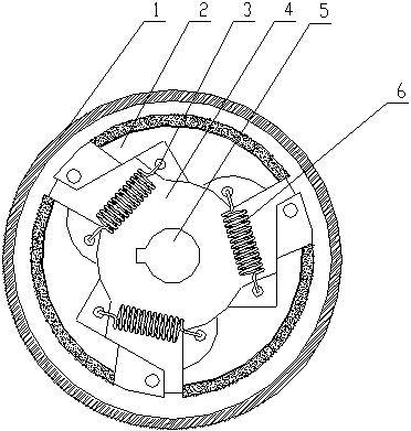
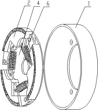
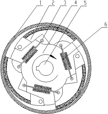
[0011] Such as figure 1 , 2 , Shown in 3, a kind of wind power generator speed limiting device is made of brake disc 1 and centrifugal brake, and centrifugal brake is arranged in the brake disc 1; Centrifugal brake comprises a circular bottom plate 4 and three arc Shaped brake pads 2, the center of the circular base plate 4 is provided with a coupling groove 5, three arc-shaped brake pads 2 are movably connected on the base plate 4, and the arc-shaped sides of the three brake pads 2 form an outer circle with the circular base plate 4 Concentric circles, two through holes 3 are respectively opened on each brake pad 2 , and tension springs 6 are arranged between two adjacent through holes 3 of two adjacent brake pads 2 .


PUM


Abstract

The invention discloses a wind driven generator speed limiting device, and belongs to the technical field of power equipment. The device consists of a brake disc and a centrifugal brake, wherein the centrifugal brake is arranged in the brake disc and comprises a circular bottom plate and three cambered brake sheets; a connecting shaft groove is formed in the center of the circular bottom plate; the three cambered brake sheets are movably connected to the bottom plate; cambered edges of the three cambered brake sheets form a circle which is concentric with the outer circle of the circular bottom plate; each brake sheet is provided with two through holes respectively; and a tension spring is arranged between two adjacent through holes of two adjacent brake sheets. Through the device, the safety of a product is improved, the mounting, maintenance or replacement is extremely convenient, and after-sales service cost and mounting cost of a manufacturer are greatly reduced; compared with an electronic speed limiting device, the device has a more direct effect, does not depend on the functions of other components and has high stability, and the safety is completely guaranteed; and the device is arranged in a fan without affecting the appearance.

Description

technical field [0001] The invention belongs to the technical field of electric power equipment, and in particular relates to a speed limiting device of a wind power generator. Background technique [0002] For a long time, small wind turbines have always been a major safety hazard. When encountering strong winds, small wind turbines rotate at high speed and generate huge centrifugal force, which can easily cause the blades to fly out. The passing rate when passing through the blade is greatly reduced, and the wind pressure on the blade becomes larger, causing the blade to bend, deform, or even break, which is likely to cause a safety accident. [0003] In response to the above situation, some small wind turbines currently integrate electronic speed limiting devices in the controller, and use the electronic system to monitor the current or voltage to indirectly control the speed. However, in the process of use, it is found that the failure rate of the controller is relativel...

Claims


Application Information

Patent Timeline
Patent Type & Authority Applications(China)
IPC IPC(8): F03D7/00F16D59/00
CPCY02E10/723Y02E10/72Y02P70/50
Inventor 陈玉田
Owner 陈玉田
Why Eureka
Try Eureka