
High pressure discharge lamp

A technology for high-pressure discharge lamps and discharge capacitors, applied in the direction of discharge lamps, gas discharge lamps, discharge tubes, etc.

Inactive Publication Date: 2011-06-22
OSRAM GMBH
View PDF2 Cites 2 Cited by
  • Summary
  • Abstract
  • Description
  • Claims
  • Application Information

AI Technical Summary

Problems solved by technology

[0004] However, the application of such plastic housings is limited to lamps with low operating temperatures, since otherwise no suitable plastics are available

Method used


Image

  • High pressure discharge lamp
  • High pressure discharge lamp
  • High pressure discharge lamp

Examples


Embodiment Construction

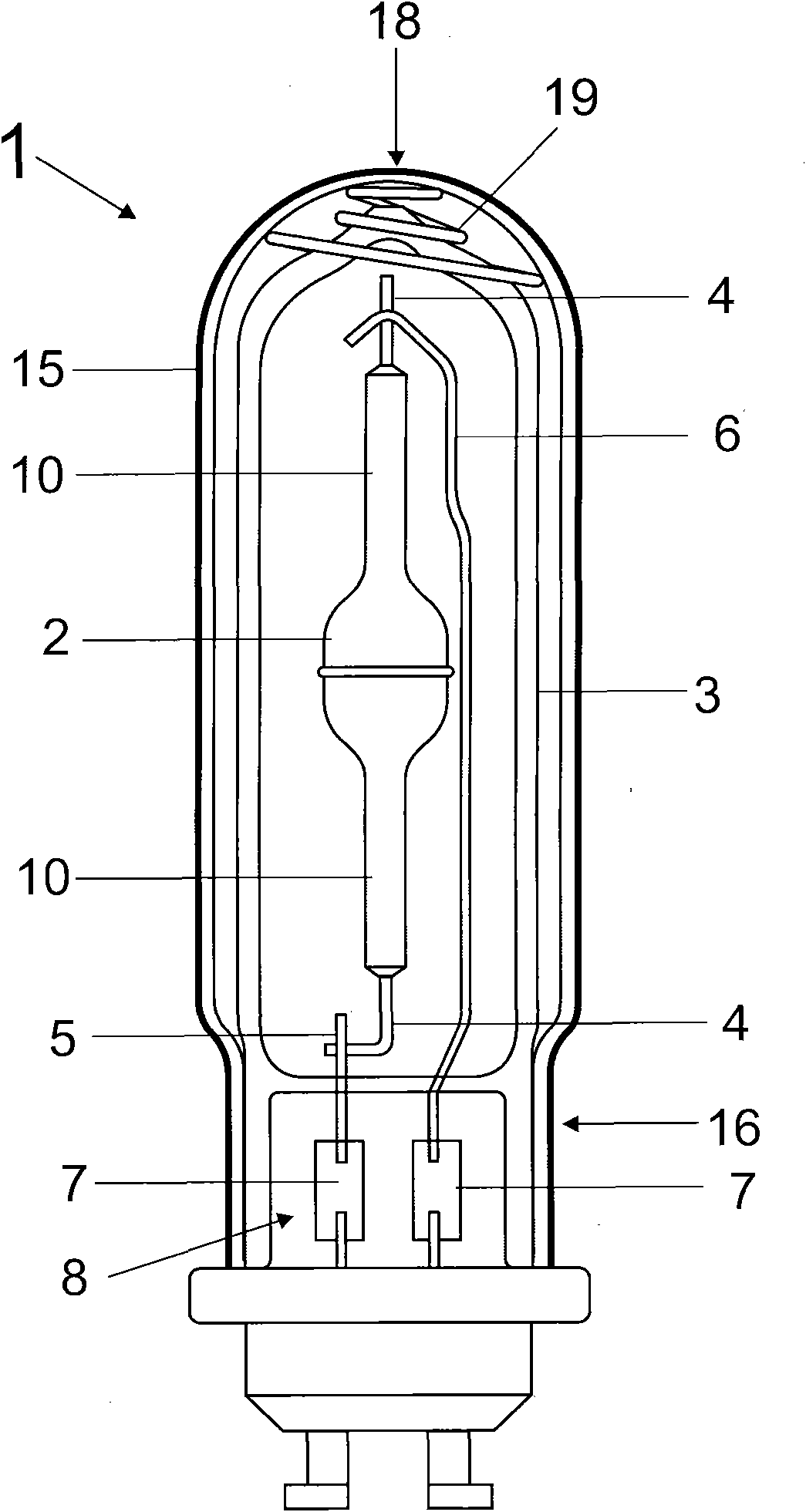
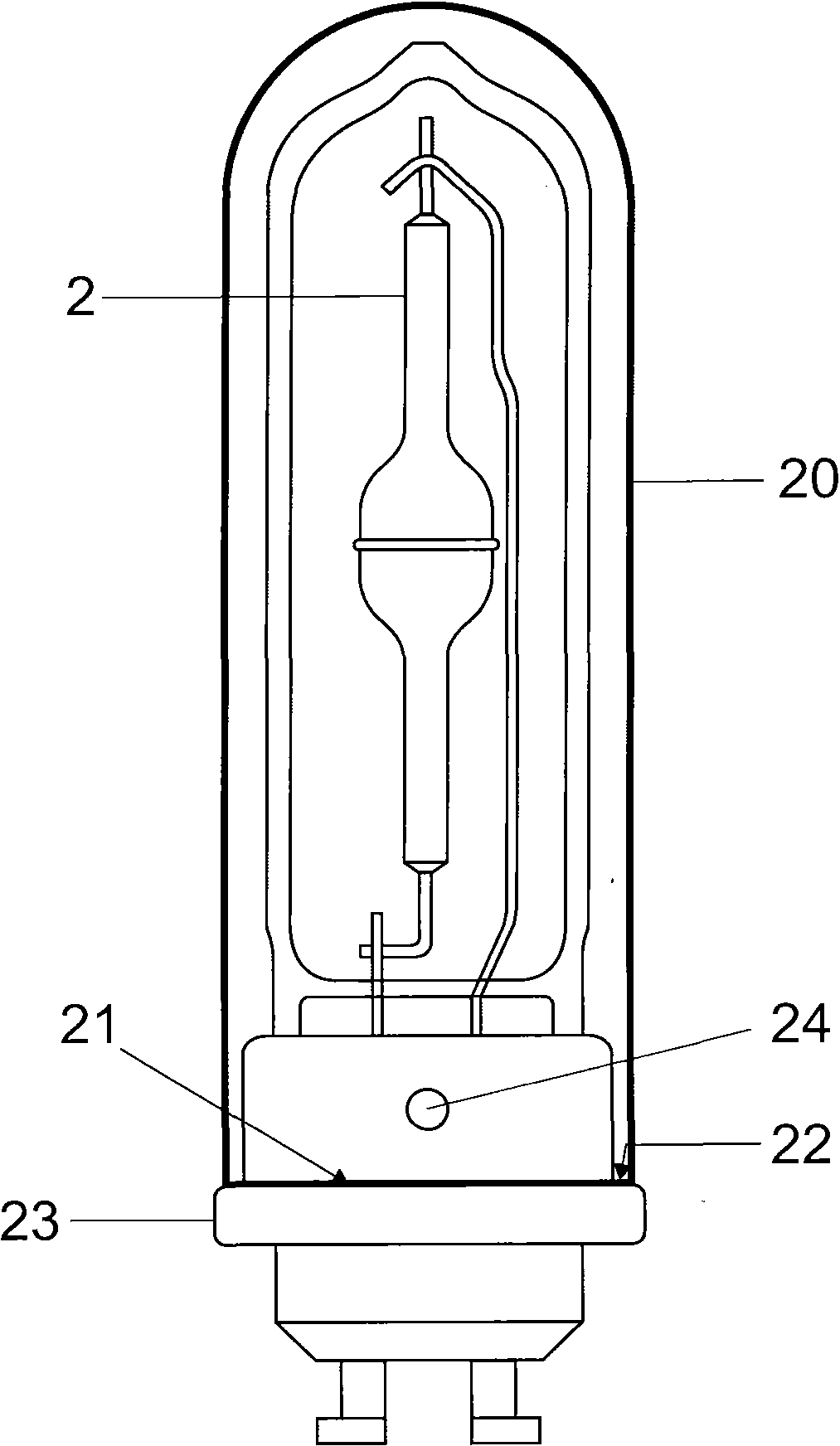
[0027] figure 1 The structure of the high-pressure discharge lamp 1 is shown strongly schematically. The high-pressure discharge lamp 1 has a discharge vessel 2 as a base lamp, which is accommodated in an outer bulb 3 . The outer lead 4 of the discharge vessel, which contacts the electrodes in the interior, is connected to two support cables 5 and 6 . The short bracket cable 5 leads to the first foil 7 in the pinch 8 of the outer bulb. Long support cables 6 , often called arc cables, lead to the second foil 7 of the pinch 8 . The discharge vessel 2 has, as known per se, at its ends a capillary 10 each, and also has, as known per se, a capillary tube made of ionizable gas (usually argon or xenon), mercury and metal halides. of fillers. As is also known per se, two electrodes lie opposite each other in the interior of the discharge vessel and are not shown here.

[0028] The outer bulb 3 is surrounded by a second outer bulb or cover 15 made of hard glass, which abuts agains...


PUM


Abstract

The present invention relates to a high pressure discharge lamp which is provided with a ceramic discharge vessel that is accommodated in an outer bulb, wherein the outer bulb is surrounded by a second outer bulb which is close to the outer bulb for fragment protection. The second outer bulb is fixed in a horizontal direction of a lamp holder.

Description

technical field [0001] The invention is based on a high-pressure discharge lamp according to the preamble of claim 1 . Such lamps are in particular high-pressure discharge lamps for general lighting or for photographic purposes. Background technique [0002] EP 1 652 212 discloses a high-pressure discharge lamp having a ceramic discharge vessel which is protected against splinters by being surrounded by two envelopes. [0003] WO 2008 / 022929 discloses a discharge lamp which is enclosed by a plastic housing, in particular for the purpose of protection against splinters. [0004] However, the application of such plastic housings is limited to lamps with low operating temperatures, since otherwise no suitable plastics are available. Contents of the invention [0005] It is the object of the invention to provide a high-pressure discharge lamp according to the preamble of claim 1 which is compact and still has sufficient burst protection. [0006] This applies in particular ...

Claims


Application Information

Patent Timeline
Patent Type & Authority Applications(China)
IPC IPC(8): H01J61/30H01J61/34H01J61/36F21Y101/00
CPCH01J61/302H01J5/54H01J61/34
Inventor 约阿希姆·阿恩特乌韦·菲德勒拉尔夫·豪席尔德
Owner OSRAM GMBH
Learn More