Cutting insert and cutting tool

A technology of cutting inserts and insert holders, which is applied in the field of cutting tools and can solve problems such as difficulty in using sintered crystal whiskers

Inactive Publication Date: 2011-06-22
NGK SPARK PLUG CO LTD
View PDF6 Cites 7 Cited by
  • Summary
  • Abstract
  • Description
  • Claims
  • Application Information

AI Technical Summary

Problems solved by technology

Patent Document 2 says nothing about the method of manufacturing ceramics including whiskers, and it is difficult to sinter crystal whiskers using a technique that causes residual stress in ceramics

Method used


Image

  • Cutting insert and cutting tool
  • Cutting insert and cutting tool
  • Cutting insert and cutting tool

Examples


Embodiment Construction

[0040] In order to simultaneously improve crack resistance and wear resistance, the inventors of the present invention realized the cutting edge of the present invention with original insight, which will be described below.

[0041] In order to manufacture a cutting edge made of ceramics excellent in crack resistance, it is necessary for the ceramics to include whiskers. Therefore, we have studied a cutting insert having a cutting edge made of ceramics to which SiC whiskers are added instead of ceramics containing SiC fine powder contained in the cutting edge prepared in the example disclosed in Patent Document 2 above.

[0042] When grinding ferrous materials with cutting inserts made of ceramics containing a large number of whiskers, the whiskers wear themselves out. Therefore, in order to improve the wear resistance of the cutting insert, it is necessary to reduce the amount of whiskers. On the other hand, when the amount of whiskers is reduced for the purpose of wear resi...


PUM

PropertyMeasurementUnit
residual stressaaaaaaaaaa
particle sizeaaaaaaaaaa
thicknessaaaaaaaaaa

Abstract

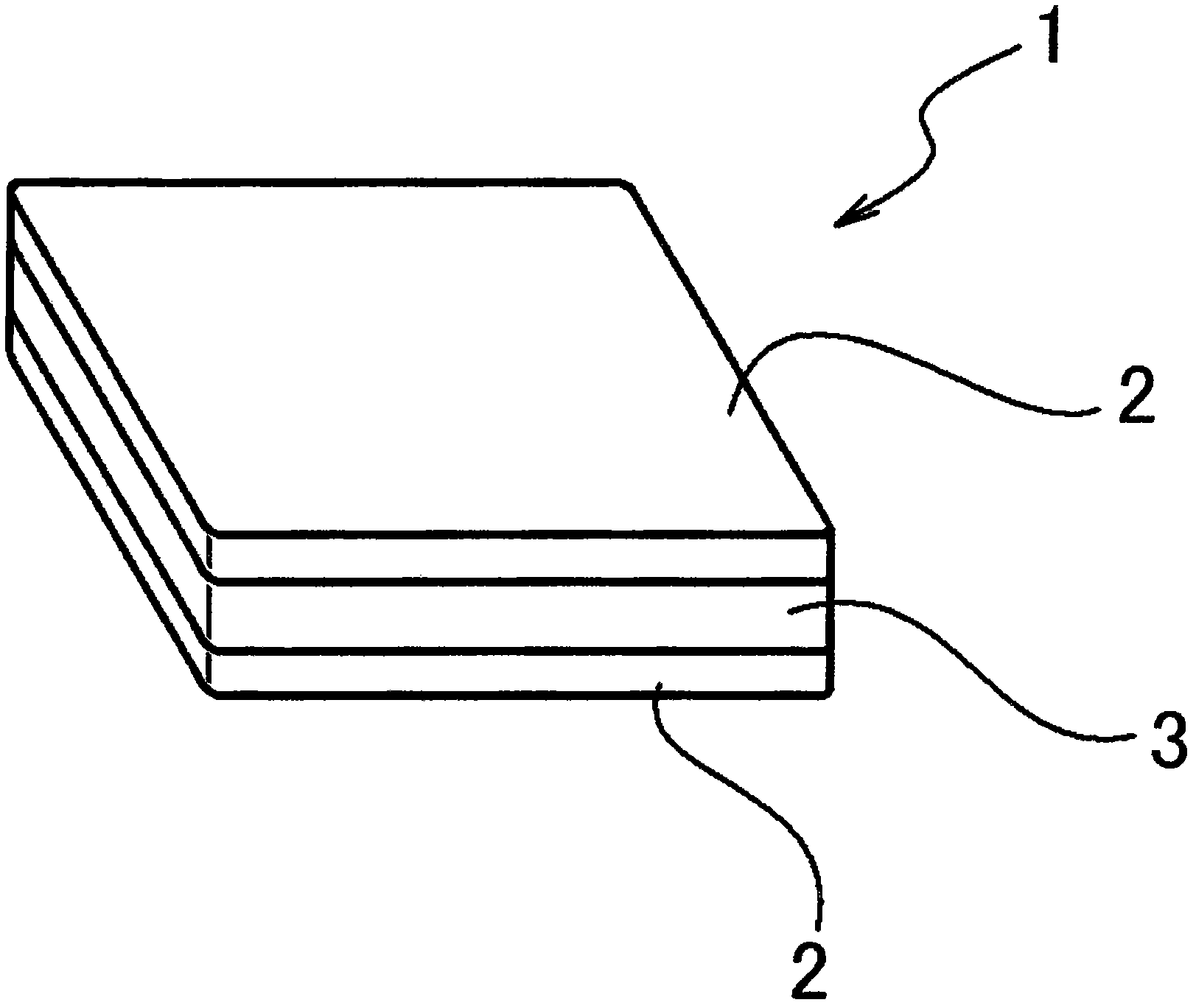
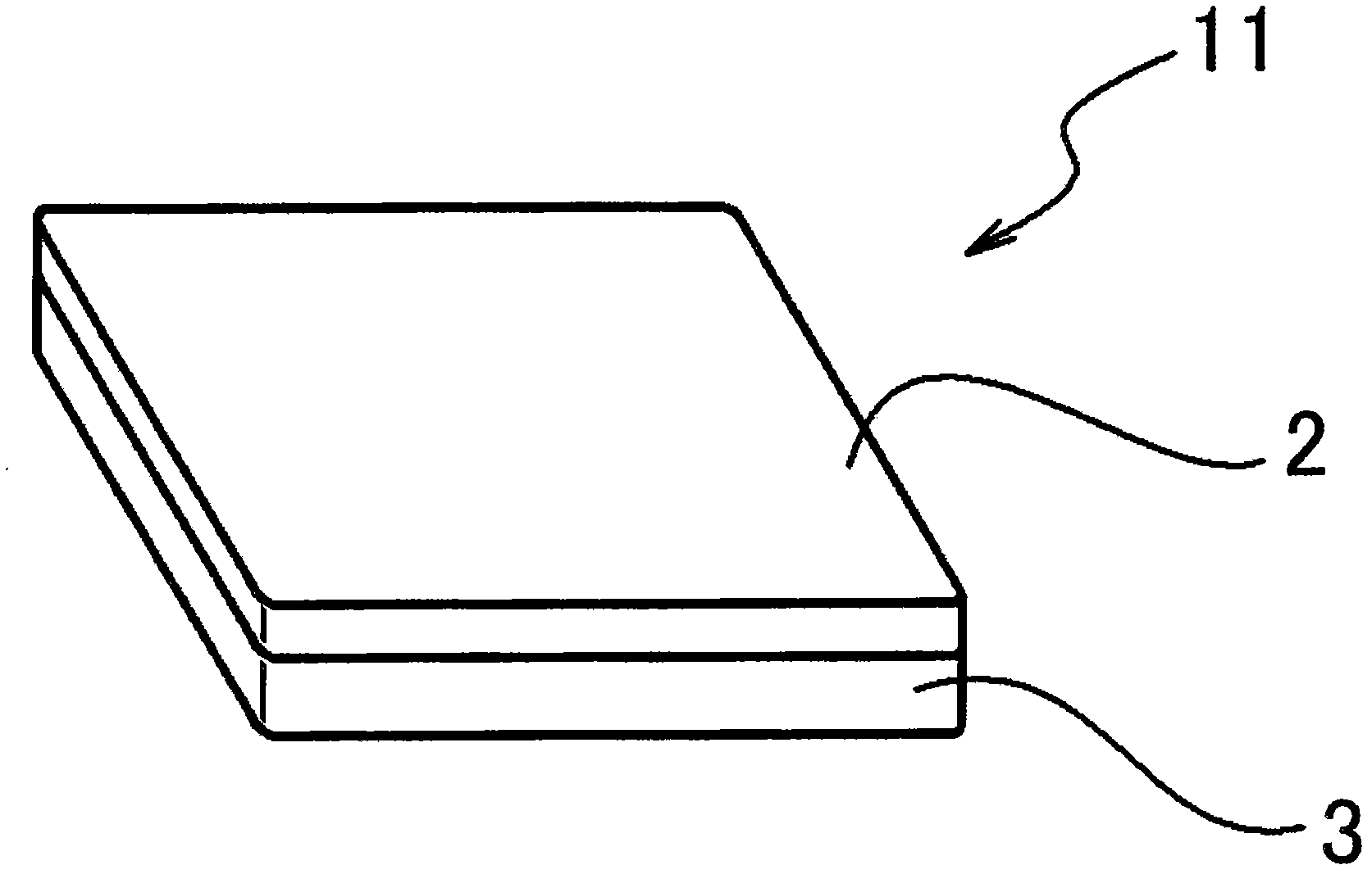
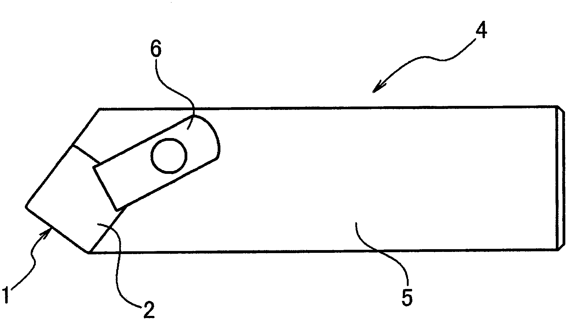
Provided are a cutting insert and a cutting tool, capable of maintaining cutting performance for a long time . The cutting insert has a cutting blade made of a ceramic including the base and the cutting blade integrated with each other, wherein the base has a first coefficient of thermal expansion larger than a second coefficient of thermal expansion that the cutting blade has; and a difference between the first coefficient and the second coefficient is from more than 0 ppm to not more than 3 ppm.

Description

technical field [0001] The present invention relates to a cutting insert and a cutting tool, and more particularly, to a cutting insert capable of maintaining cutting performance for a long period of time and a cutting tool equipped with the cutting insert. Background technique [0002] Patent Document 1 discloses a cutting edge portion and a 2 o 3 Al other parts made of particulate material 2 o 3 - SiC whisker cutting tool, the cutting edge portion has a thickness of 2 mm or more and 4 mm or less and is made of Al 2 o 3 - SiC whisker material to provide SiC reinforced Al 2 o 3 Whisker cutting tools having a cost-performance ratio sufficient for cutting ferrous materials such as gray iron and ductile iron and containing reduced amounts of expensive SiC whiskers. (see paragraph [0004] of patent document 1, claim 1 and figure 1 ). [0003] Patent Document 1 generally discloses that the amount of SiC whiskers contained in the formed cutting edge is 7% to 40% by volume,...

Claims


Application Information

Patent Timeline
Patent Type & Authority Applications(China)
IPC IPC(8): B23B27/14B23B27/18C04B35/10C04B35/80
CPCB23B2226/72C04B35/80B23B27/141C04B35/10B23B2228/61B23B2224/04B23B2226/18Y10T407/27B23B27/14B23B27/18
Inventor 虻川宏平浦岛和浩铃木友辅伊藤达也丰田亮二上川弘二
Owner NGK SPARK PLUG CO LTD
Why Eureka
Try Eureka