Electric vacuum cleaner

A vacuum cleaner, electric technology, applied in the direction of vacuum cleaners, household appliances, cleaning equipment, etc., can solve the problem of the position deviation of the exhaust filter, rolling up the floor surface, etc., to achieve the effect of clear parts, stable flow and good appearance

Inactive Publication Date: 2011-06-29
SANYO ELECTRIC CO LTD +1
View PDF4 Cites 0 Cited by
  • Summary
  • Abstract
  • Description
  • Claims
  • Application Information

AI Technical Summary

Problems solved by technology

[0007] In the electric vacuum cleaner of Patent Document 1, in the main body of the vacuum cleaner, the position of the exhaust filter may be shifted due to the wind pressure of the air flowing out of the dust collector.
[0008] In addition, in the electric vacuum cleaner of Patent Document 1, since the air is discharged to the outside from the exhaust port formed only at the lower part of the front surface of the main body of the vacuum cleaner, the flow force of the air discharged from the exhaust port is relatively strong. Dust on the floor surface is rolled up by the exhausted air

Method used


Image

  • Electric vacuum cleaner
  • Electric vacuum cleaner
  • Electric vacuum cleaner

Examples


Embodiment Construction

[0055] Hereinafter, embodiments of the present invention will be specifically described with reference to the drawings.

[0056]

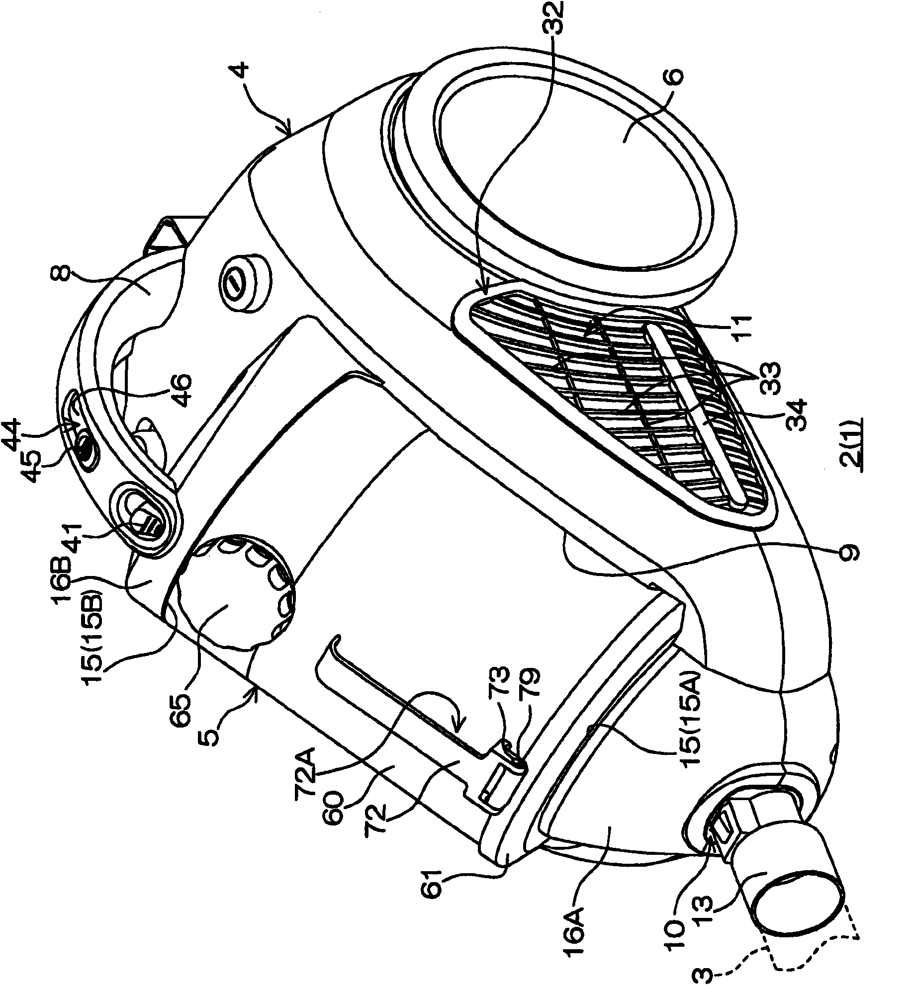
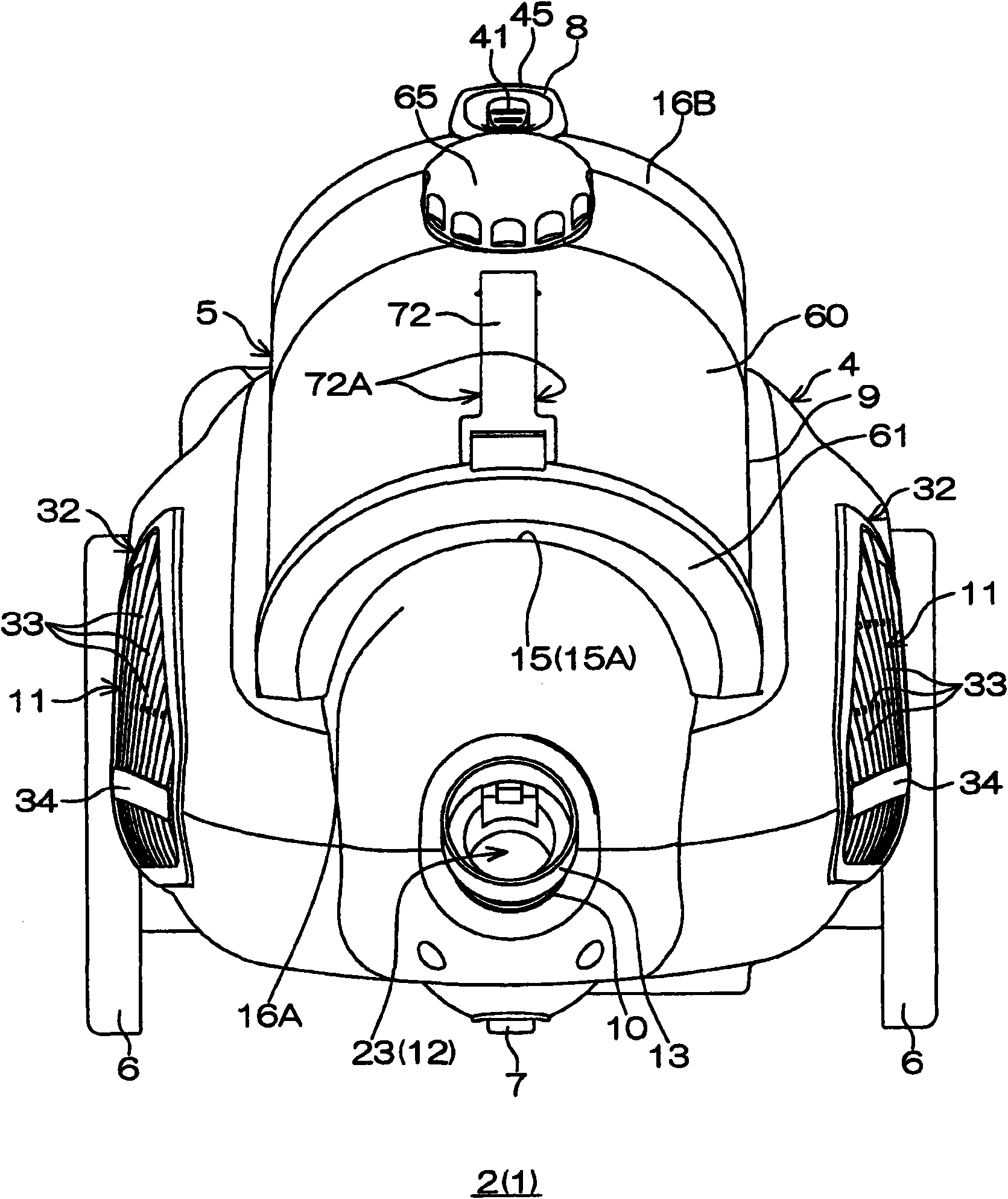
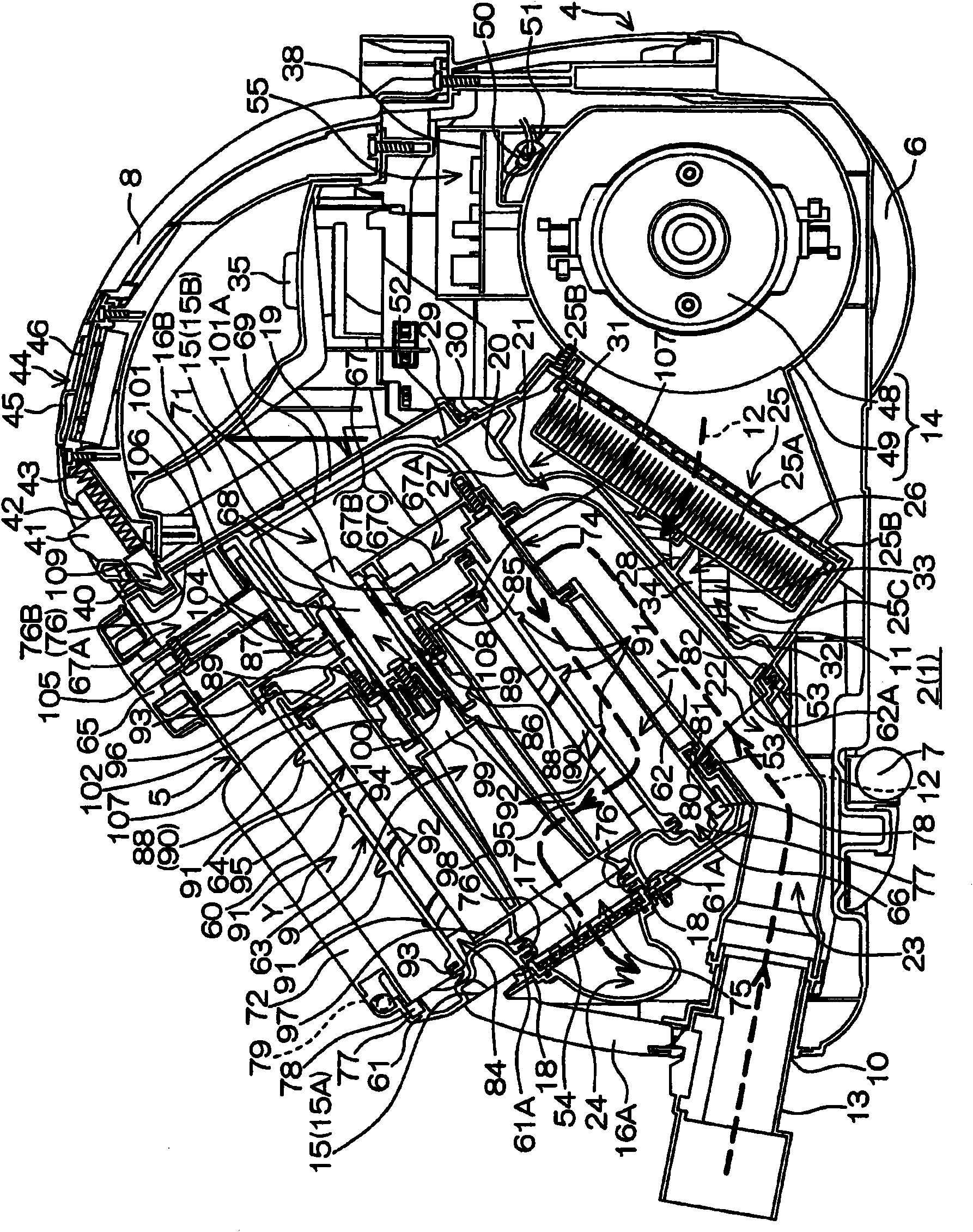
[0057] figure 1 It is a perspective view of the vacuum cleaner main body 2 of the electric vacuum cleaner 1 which concerns on one Embodiment of this invention seen from the front side. figure 2 It is a front view of the vacuum cleaner main body 2 . image 3 It is a sectional view of the right side of the cleaner main body 2 . here, in figure 1 In the description, the lower left side is taken as the front side of the electric vacuum cleaner 1, the upper right side is taken as the rear side of the electric vacuum cleaner 1, the upper left side is taken as the left side of the electric vacuum cleaner 1, and the lower right side is taken as the right side of the electric vacuum cleaner 1. In the following Similarly in the description, when a direction is specified, front and rear, left and right, and up and down of electric vacuum cleaner 1 are spe...


PUM


Abstract

The invention provides an electric vacuum cleaner which can locate an exhaust filter by a simple structure. In the electric vacuum cleaner (1), an electric blower (14) disposed in a frame (4) sucks air and dust together from an air suction inlet (10) to allow the air and the dust to flow in a flow path (12), to allow the sucked dust to accumulate in a dust collecting box (5), and to allow the sucked air to be discharged from an exhaust port (11). An exhaust filter (26) disposed in the flow path (12) prevents the passage of the dust mixed in the air discharged by the electric blower (14). In the flow path (12), a cover (27) for the location of the exhaust filter is disposed at the downstream side of the exhaust filter (26) when observed in the flow direction of the discharged air. The cover is disposed in the frame in a manner that the dust collecting box is pressed to the exhaust filter, so the cover can locate the exhaust filter without migration even if the exhaust filter is migrated to the downstream side by the wind pressure of the discharged air.

Description

technical field [0001] The present invention relates to electric vacuum cleaners. Background technique [0002] There is known an electric vacuum cleaner including a vacuum cleaner main body with a built-in electric blower and a dust collector detachably attached to the vacuum cleaner main body (see Patent Document 1). [0003] The dust collecting device of Patent Document 1 includes a substantially cylindrical dust collecting case extending longitudinally, a cylindrical prefilter attached inside the dust collecting case, and a main filter attached inside the prefilter. [0004] The air and dust sucked into the main body of the vacuum cleaner by the suction force generated by the electric blower swirls in the dust collection case and flows downward, and the dust is accumulated on the bottom surface of the dust collection case in a compressed state. In addition, part of the dust will pass through the coarse filter, and at this time, it will be captured by the coarse filter a...

Claims


Application Information

Patent Timeline
Patent Type & Authority Applications(China)
IPC IPC(8): A47L9/00
Inventor 古家义也中井康一小寺定基福冈秀俊
Owner SANYO ELECTRIC CO LTD
Why Eureka
Try Eureka