Electronic thermometer and body temperature measurement method

An electronic thermometer and temperature measurement technology, which is applied in the direction of body temperature measurement, thermometers, measuring devices, etc., can solve problems such as inability to derive deep body temperature

Active Publication Date: 2011-06-29
SEIKO EPSON CORP
View PDF5 Cites 19 Cited by
  • Summary
  • Abstract
  • Description
  • Claims
  • Application Information

AI Technical Summary

Problems solved by technology

Due to lateral heat movement in the body, the peripheral part of the thermometer is cooler than the central part, and due to this effect, an accurate deep body temperature may not be derived

Method used


Image

  • Electronic thermometer and body temperature measurement method
  • Electronic thermometer and body temperature measurement method
  • Electronic thermometer and body temperature measurement method

Examples


Embodiment 1

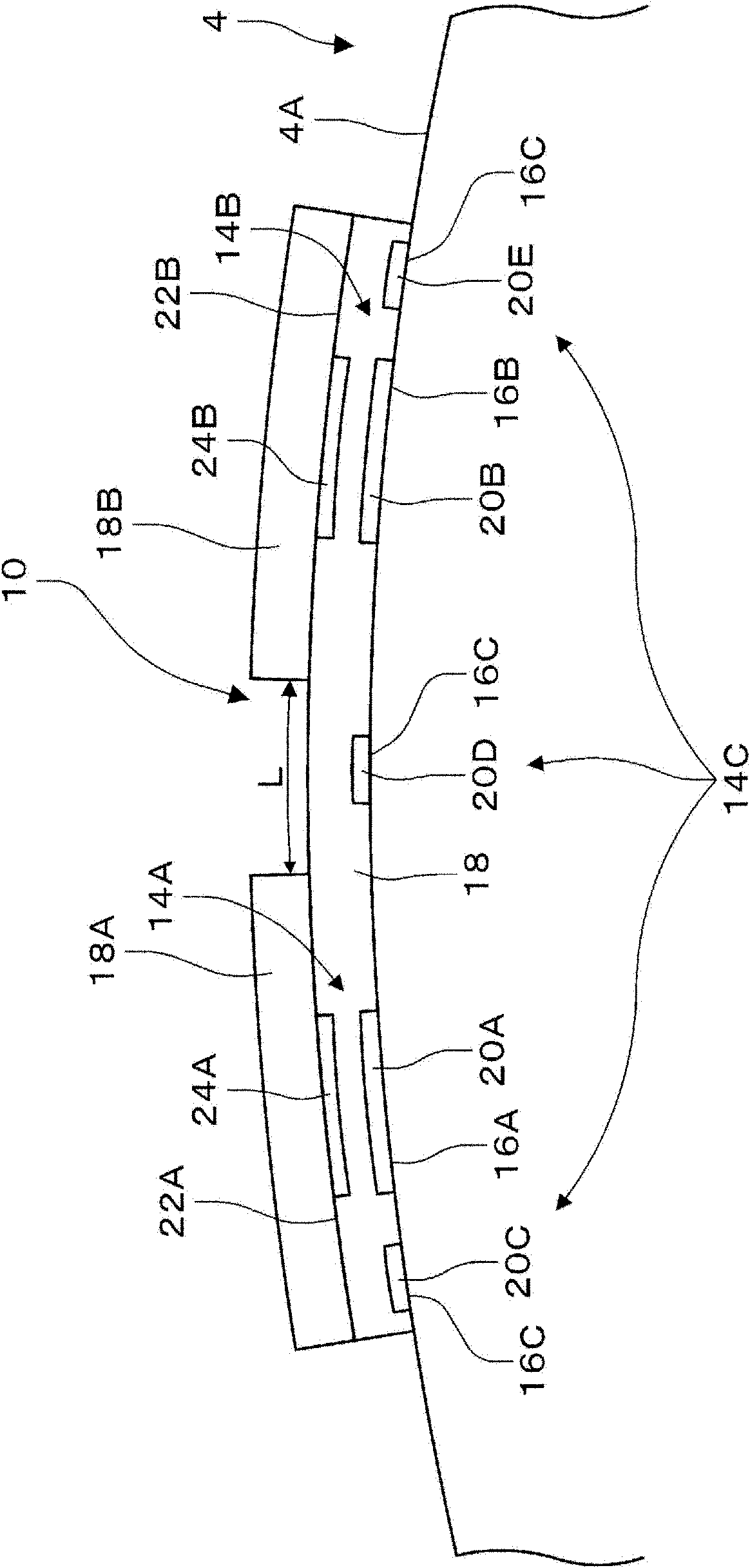
[0101] Figure 5 It is a figure which shows the structure of the thermometer main body 10 of this embodiment. In addition, Figure 5 (A) is a perspective view of the thermometer body 10, Figure 5 (B) is a cross-sectional view of the thermometer body 10, Figure 5 (C) is a diagram showing an example of the arrangement of body surface sensors 20C, 20D, and 20E for calibration.

[0102] Such as Figure 5 As shown in (A), the thermometer main body 10 has a thin cylindrical shape with a step difference on the upper surface. Such as Figure 5 As shown in (B), the clinical thermometer body 10 has body surface sensors 20A, 20B as temperature sensors (thin film thermistors), body surface sensors 20C, 20D, and 20E for calibration, and first and second heat radiation control units 18A, 18B. The thermometer main body 10 is configured such that a second heat dissipation control unit 18B having a different thermal conductivity is attached to the upper half of the first heat dissipation contro...

Embodiment 2

[0114] Picture 11 It is a figure which shows the structure of the thermometer main body 10 of this embodiment. In addition, Picture 11 (A) is a perspective view of the thermometer body 10, Picture 11 (B) is a cut out of the temperature measuring part 46, Picture 11 (C) and (D) are cross-sectional views of the main body 10 of the clinical thermometer.

[0115] Thermometer body 10 such as Picture 11 As shown in (A), the temperature measuring part is surrounded by the heat insulating part 18, and heat is transferred one-dimensionally. Thermometer body 10 such as Picture 11 As shown in (B), the thermal resistance of the temperature measuring unit 46 is equal, but the first and second heat dissipation control units 18A, 18B are provided with substances with different thermal conductivity in the part in contact with the outside air in a different temperature distribution. . For example Picture 11 As shown in (C), so that the temperature distribution of the first system 44A and ...

Embodiment 3

[0126] Figure 16 It is a cross-sectional view showing the temperature distribution of the body surface when the thermometer main body 10 of this embodiment is worn, and a diagram showing an example of arrangement. Figure 17 It is a figure which shows the example of arrangement|positioning of the body surface sensors 20C, 20D, and 20E for calibration of this embodiment. In addition, Figure 16 (A) is a cross-sectional view showing the temperature distribution of the body surface when the thermometer body 10 is worn, Figure 16 (B) and (C) are diagrams showing examples of the arrangement of body surface sensors 20C, 20D, and 20E for calibration.

[0127] Such as Figure 16 As shown in (A), the body surface sensors 20C, 20D, and 20E for calibration are added to detect Picture 12 (B) The curve of the temperature distribution of only the heat insulating portion 18. Such as Figure 16 As shown in (B), the body surface sensors 20C, 20D, and 20E for calibration at this time and the tem...


PUM


Abstract

The invention provides an electronic thermometer and a body temperature measurement method which can correctly measure core body temperature. An electronic thermometer (2) includes a first body surface temperature measurement portion (20A) and a second body surface temperature measurement portion (20B), a first reference temperature measurement portion (24A) and a second reference temperature measurement portion (24B), a third body surface temperature measurement portion (20C, 20D, 20E) to measure values at each position having a predetermined thermal resistance relative to a measurement a third temperature with a position different from the measurement positions of the first and second body surface values, a temperature correction portion (40) to correct a first body surface temperature, a first reference temperature, a second body surface temperature, and a second reference temperature by a third temperature; and a core body temperature calculation portion (42) to calculate a value of the object using the obtained corrected values of a first body surface temperature, a first reference temperature, a second body surface temperature, and a second reference temperature.

Description

Technical field [0001] The invention relates to an electronic clinical thermometer and a method for measuring body temperature. Background technique [0002] When measuring human body temperature, the thermometer needs to be stored under the tongue, underarms, rectum, etc., until the thermometer and body temperature are in temperature balance. These are places that reflect the internal temperature of the body called deep temperature, and are performed as general body temperature measurement. On the other hand, in a continuous deep clinical thermometer that is continuously worn on the body surface, there is a method in which a heater is installed, and the temperature at which the heat flow from the inside of the body, that is, the deep part, and the heat flow from the heater are equal is used as the deep body temperature. However, because the heater is installed, the power is increased, and the device is enlarged due to the need for control, and it cannot be used continuously in ...

Claims


Application Information

Patent Timeline
Patent Type & Authority Applications(China)
IPC IPC(8): A61B5/01
CPCA61B5/6833A61B5/01G01K7/42A61B2560/0252A61B5/0008G01K13/002G01K7/427G01K13/20A61B5/7235
Inventor 后藤健次
Owner SEIKO EPSON CORP
Why Eureka
Try Eureka