Roller shifting method for controlling deviation of steel strip

A technology for controlling belt and roll shifting, which is applied in metal rolling, manufacturing tools, metal rolling, etc., can solve the problems of damage to unit equipment, long cycle time, large investment, etc., to improve rolling stability, increase production efficiency, The effect of improving product quality

Inactive Publication Date: 2011-06-29
ANGANG STEEL CO LTD
View PDF0 Cites 18 Cited by
  • Summary
  • Abstract
  • Description
  • Claims
  • Application Information

AI Technical Summary

Problems solved by technology

[0002] At present, in the actual production of hot continuous rolling, due to the influence of factors such as lateral temperature unevenness and wedge shape, the degree of lateral wear of the rolls is also different, that is, the wear is asymmetrically distributed, and often several stands are the same. The side (drive side or working side) wears a lot, so that the strip steel is forced to deviate to the side where the wear of the roll is large during the rolling process, which not only affects the quality of the strip steel, but even damages the equipment of the unit, and greatly affects the rolling stability
[0003] There are a lot of documents about strip deviation control at present, and the documents closer to the present invention have: 1) Wang Jing. Design and Analysis of the Hydraulic Servo System for Strip deviation Control, Journal of Chongqing Industrial College, 1999, 14 (3): 51-53.2) He Anrui, Zhang Qingdong. Metallurgical Equipment for the Exploration of Strip Deviation in Hot Continuous Rolling and Finishing Mills, 1998, 12: 51-53. The strip deviation control methods and devices disclosed in the above documents are to a certain extent On the one hand, it prevents the deviation of the strip and improves the stability of the strip rolling, but it needs to add new equipment, which requires a large investment and a long cycle

Method used


Image

  • Roller shifting method for controlling deviation of steel strip
  • Roller shifting method for controlling deviation of steel strip
  • Roller shifting method for controlling deviation of steel strip

Examples


Embodiment Construction

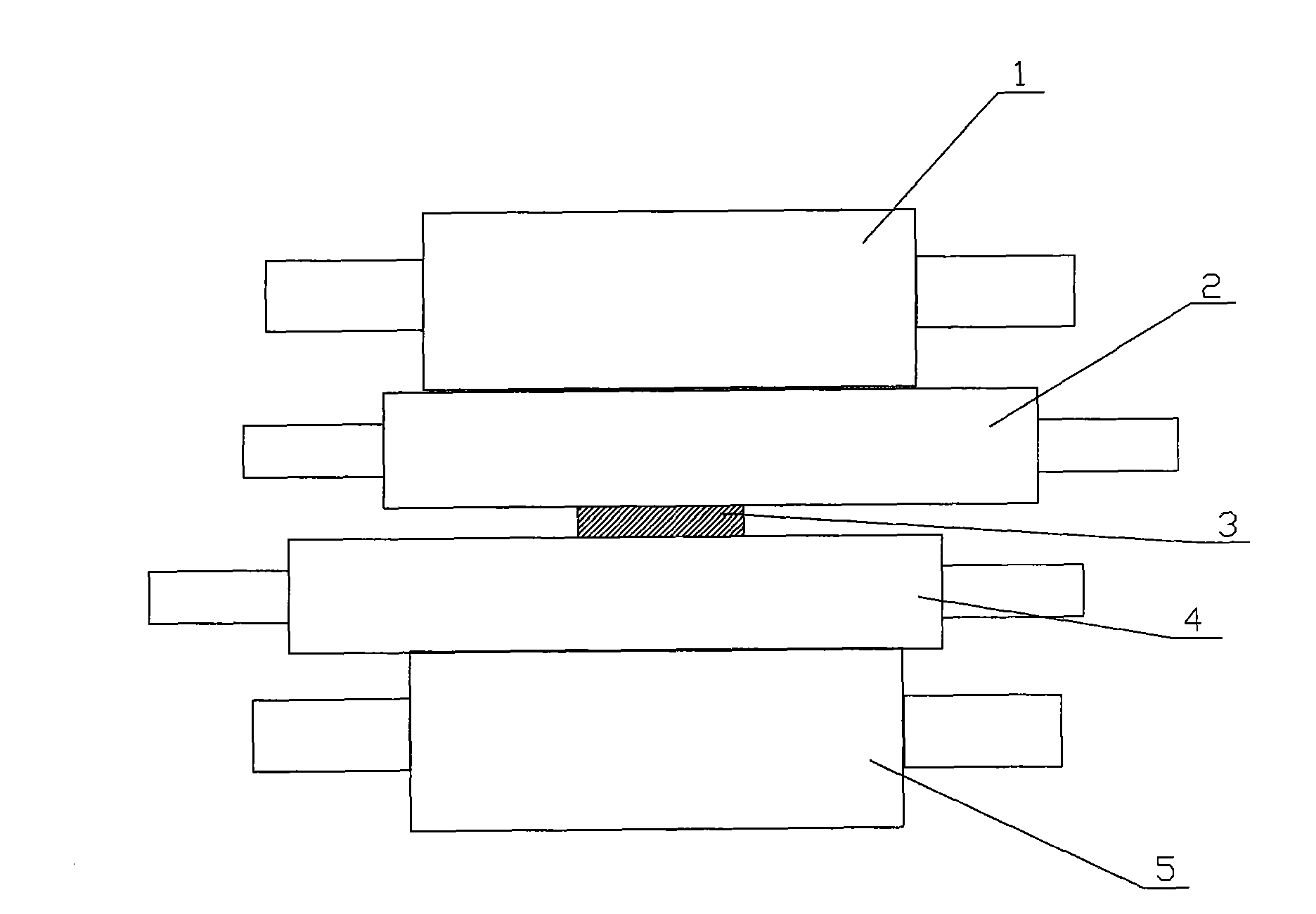
[0017] The specific embodiment of the present invention will be further described below in conjunction with accompanying drawing:

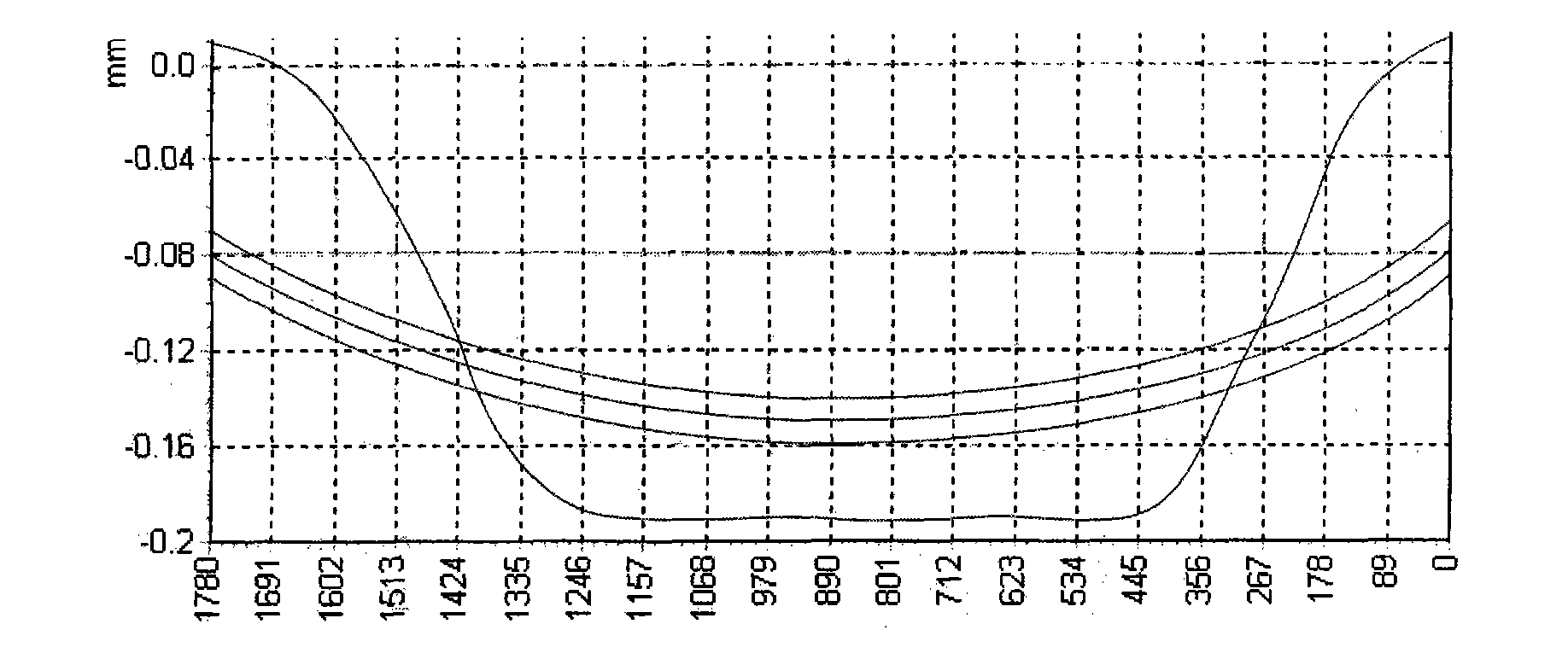
[0018] See figure 1 , when the hot continuous rolling finishing mill is rolling, the upper work roll 2 and the upper back-up roll 1 are arranged on the strip steel 3 and the lower work roll 4 and the lower back-up roll 5 are arranged below, and the upper work roll 2 and the lower work roll 4 are due to Affected by factors such as uneven lateral temperature and wedge shape of strip steel 3, the degree of wear is also different, showing an asymmetric distribution. The wear curve is shown in Figure 4 , and often several racks have the same side with large wear, so that the strip will be forced to deviate to the side with large roll wear during the rolling process, which will not only affect the quality of the strip, but even damage the equipment of the unit , and greatly affects the rolling stability.

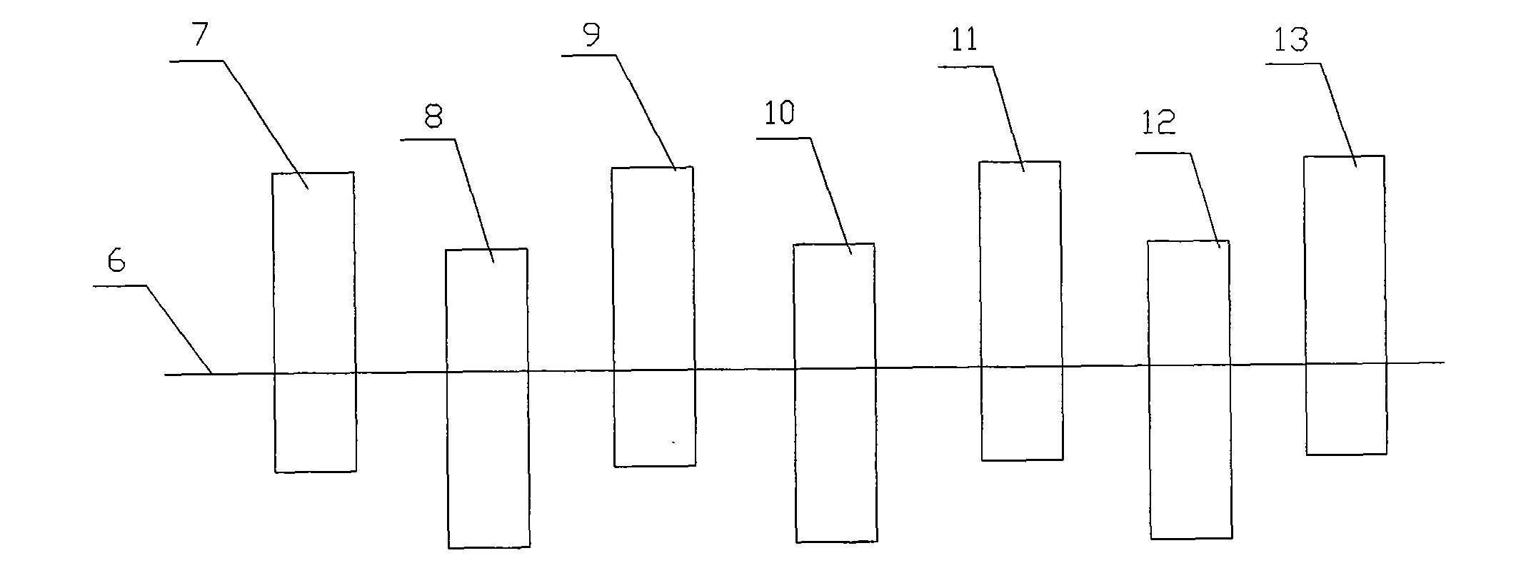
[0019] See figure 2 , a roll shifting meth...


PUM


Abstract

The invention relates to the field of steel rolling, in particular a roller shifting method for controlling the deviation of a steel strip during a production process of a hot continuous rolling and finish rolling unit. By setting a roller shift frequency, a crossed roller shift mode and a roller shift step value of working rollers of two adjacent frames, the worn working rollers of two adjacent frames are crossed and shifted regularly. The method comprises the following steps: (1) the working rollers of the individual frames are set in initial center zero positions; (2) the working rollers of the individual frames are shifted at equal frequency in the range from 2 to 3; (3) the shift directions of two adjacent frames are opposite, and the roller shift step value is controlled within the range from 10 mm to 15 mm; and (4) the working rollers are shifted reversely when reaching the shift limit ranging from 100 mm to 150 mm. The invention has the benefits that: the roller shifting method is easy to implement and can achieve the purpose of shifting the rollers with box-shaped worn parts of two adjacent frames, so as to play the role of correcting the deviation and thus to increase the production efficiency of the hot rolling production line, stabilize the rolling condition and improve the product quality; and besides, the roller shifting method improves the transverse shift of the steel strip between the finish rolling units during the rolling process and enhances the rolling stability of the steel strip.

Description

technical field [0001] The invention relates to the field of steel rolling, in particular to a roll shifting method for controlling strip deviation in the production process of a hot continuous rolling finishing mill. Background technique [0002] At present, in the actual production of hot continuous rolling, due to the influence of factors such as lateral temperature unevenness and wedge shape, the degree of lateral wear of the rolls is also different, that is, the wear is asymmetrically distributed, and often several stands are the same. The side (drive side or working side) wears a lot, so that the strip steel is forced to deviate to the side where the wear of the roll is large during the rolling process, which not only affects the quality of the strip steel, but even damages the equipment of the unit, and greatly affects the rolling stability. [0003] There are a lot of documents about strip deviation control at present, and the documents closer to the present inventi...

Claims


Application Information

Patent Timeline
Patent Type & Authority Applications(China)
IPC IPC(8): B21B31/20
Inventor 张宪斌于斌
Owner ANGANG STEEL CO LTD
Why Eureka
Try Eureka