Method and device for automatically clamping workpieces

An automatic clamping and workpiece technology, applied in the mechanical field, can solve the problems of easy loosening of the workpiece, insufficient clamping force, inconvenient operation, etc., and achieve the effect of strong adaptability and high clamping efficiency

Inactive Publication Date: 2011-06-29
贵州省机电装备工程技术研究中心有限公司 +1
View PDF8 Cites 9 Cited by
  • Summary
  • Abstract
  • Description
  • Claims
  • Application Information

AI Technical Summary

Problems solved by technology

Clamping in these ways is inconvenient to flexibly adjust the clamping force, and it is impossible to precisely control the clamping force, which may easily cause insufficient clamping force or excessive clamping, and the workpiece is easy to loose if the clamping force is not enough, and the clamping force If it is too large, the workpiece will be clamped and damaged
Inconvenient operation and low efficiency when clamping manually

Method used


Image

  • Method and device for automatically clamping workpieces
  • Method and device for automatically clamping workpieces
  • Method and device for automatically clamping workpieces

Examples


Embodiment 1

[0025] Take the method of automatic clamping of Φ8 workpiece as an example, including the following steps:

[0026] (1) Select a suitable spring collet for the workpiece of Φ8, place the spring collet in the lock nut, install the lock nut on the spindle, and adjust the phase of the nut so that it can match the fixing hole. The fixing hole is a non-circular hole, and the shape and size of the inner hole of the fixing hole are consistent with the outer shape and size of the lock nut;

[0027] (2) In the control system, input the linear motion speed of the lock nut as 30cm / s, the rotation speed of the spindle as 2000RPM, the clamping time as 20s, and the clamping torque of the lock nut as 5N.m;

[0028] (3) Start the control system, the servo motor A starts to drive the lock nut to enter the fixing hole at a speed of 30cm / s, so that it cooperates with the fixing hole, and the servo motor A stops when it is in place (at this time, the system automatically records The starting pos...

Embodiment 2

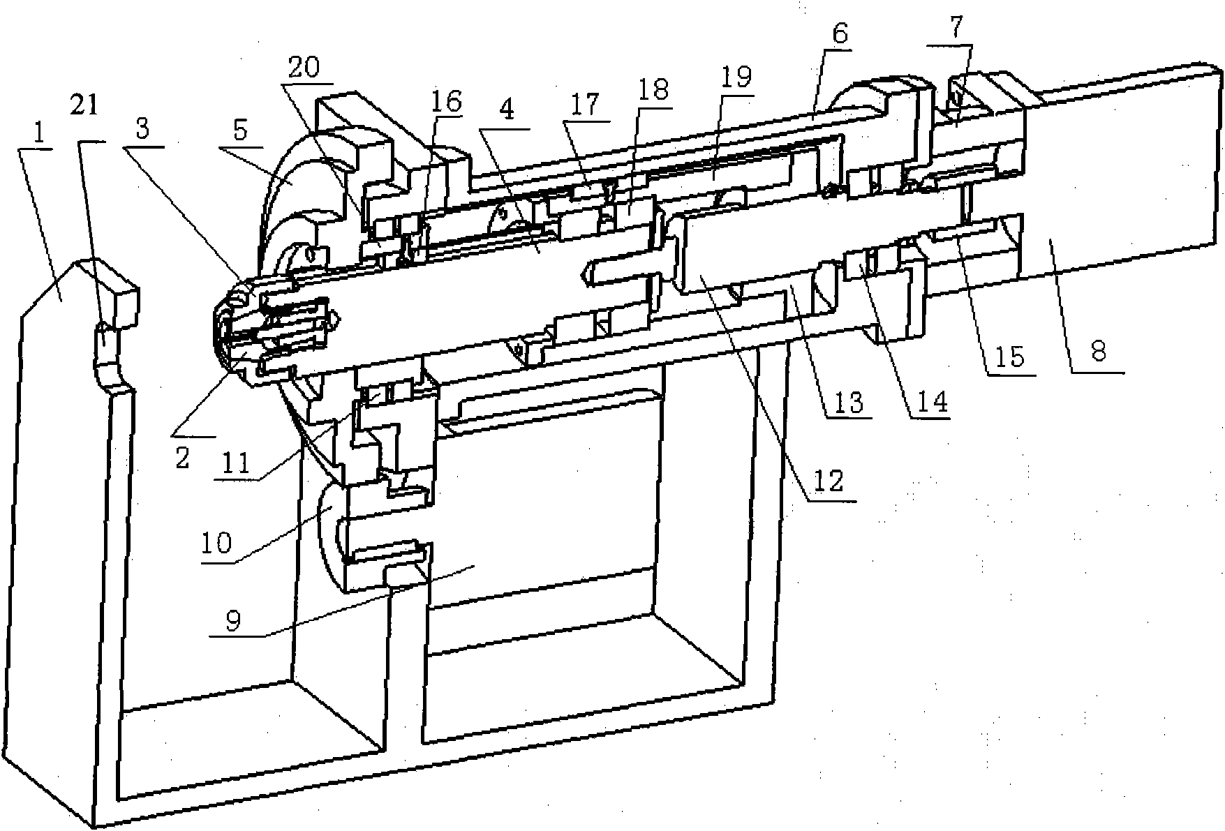
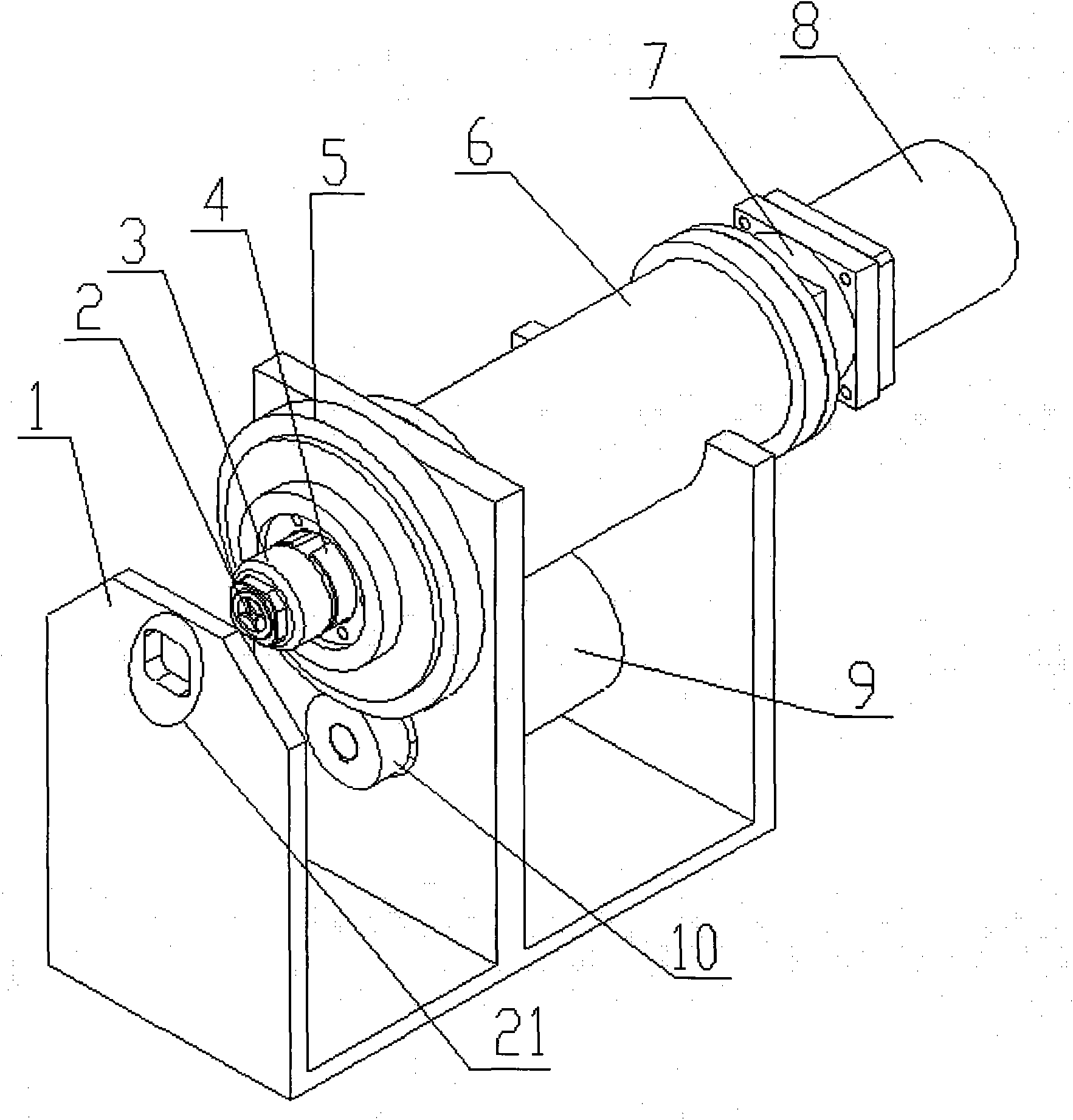
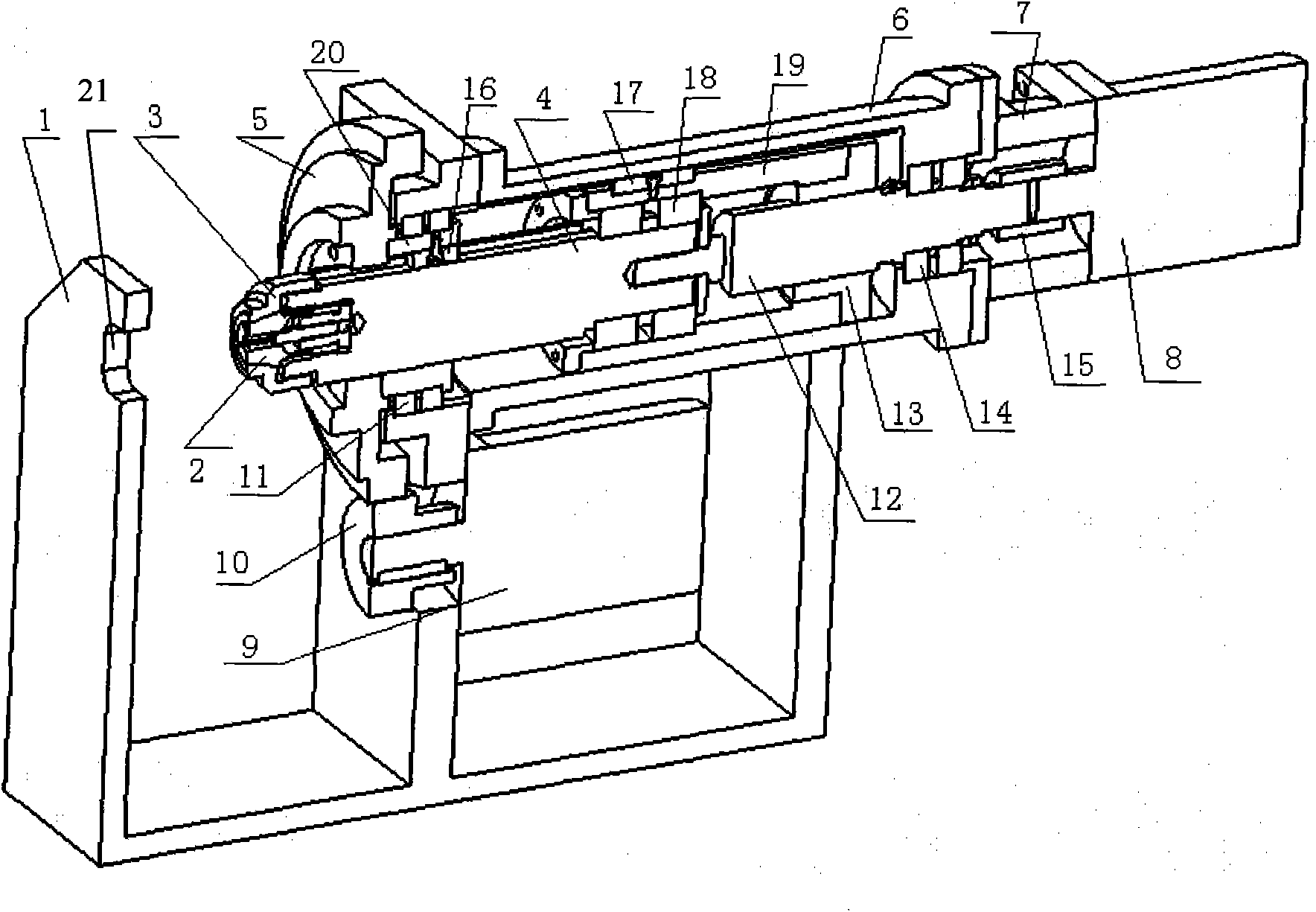
[0032] Such as Figure 1-2 As shown, the workpiece automatic clamping device includes the main shaft moving part, the main shaft rotating part, the frame 1, the sleeve A6 installed on the frame 1, the sleeve B7 connected with the sleeve A6, and the fixing hole 21 is opened on the machine. Rack 1, where:

[0033] The moving parts of the main shaft are composed of the main shaft 4, the lock nut 3 installed on the main shaft 4, the spring collet 2 which is vacantly sleeved in the lock nut 3, the bearing part A sleeved on the main shaft 4, and the The bearing part B, the lead screw nut part, and the servo motor A8 installed on the sleeve B7 are composed. The bearing component A is composed of a bearing seat 20 sleeved on the main shaft 4 , a key 16 fixed on the bearing seat 20 , and a bearing A11 installed on the bearing seat 20 . The bearing part B is composed of a bearing C18 installed on the main shaft 4, a bearing end cover fixed on the main shaft 4, a sliding sleeve 19 matc...


PUM


Abstract

The invention discloses a method and device for automatically clamping workpieces, which are characterized in that workpieces are clamped by two sets of servo systems, a fixed clamp hole is a non-circular hole, and the shape and size of an external outline of a lock nut are consistent with the shape and size of the fixed clamp hole so as to ensure the lock nut and the fixed clamp hole can be matched with each other; a set of servo system is used for driving a clamping chuck to get into (or get out of) the fixed clamp hole, so that the lock nut can be matched with the clamp hole or separated from the clamp hole; and the other set of servo system is used for adjusting the phase position of the lock nut, and driving a main shaft to have gyroscopic motion when the lock nut and the clamp hole are mutually matched, thereby achieving the purpose of clamping workpieces. By using the method and device disclosed by the invention, the clamping torque can be controlled accurately, the torque can be adjusted, the clamping position can be remembered, and the clamping operation can be completed quickly.

Description

technical field [0001] The invention belongs to the technical field of machinery, and specifically relates to a method for automatically clamping workpieces, and also relates to an automatic workpiece clamping device for realizing the method. Background technique [0002] At present, pneumatic, spring force, manual and other methods are often used to clamp workpieces. Clamping in these ways is inconvenient to flexibly adjust the clamping force, and it is impossible to precisely control the clamping force, which may easily cause insufficient clamping force or excessive clamping, and the workpiece is easy to loose if the clamping force is not enough, and the clamping force If it is too large, the workpiece will be clamped. The operation is inconvenient and the efficiency is low when manual clamping is adopted. Contents of the invention [0003] The object of the present invention is to overcome the above disadvantages and provide a method for automatic clamping of workpiec...

Claims


Application Information

Patent Timeline
Patent Type & Authority Applications(China)
IPC IPC(8): B23Q3/12
Inventor 王自勤田丰果童韬陈汉斌陈家兑刘勇
Owner 贵州省机电装备工程技术研究中心有限公司
Why Eureka
Try Eureka