
Hand-held power tool

A hand-held machine tool and flywheel quality technology, which is applied in the direction of motor tools, manufacturing tools, portable motor devices, etc., can solve problems such as reducing the moment of inertia

Active Publication Date: 2011-06-29
ROBERT BOSCH GMBH
View PDF6 Cites 2 Cited by
  • Summary
  • Abstract
  • Description
  • Claims
  • Application Information

AI Technical Summary

Problems solved by technology

However, the disadvantage of this motor is that the moment of inertia is significantly reduced

Method used


Image

  • Hand-held power tool
  • Hand-held power tool
  • Hand-held power tool

Examples


Embodiment Construction

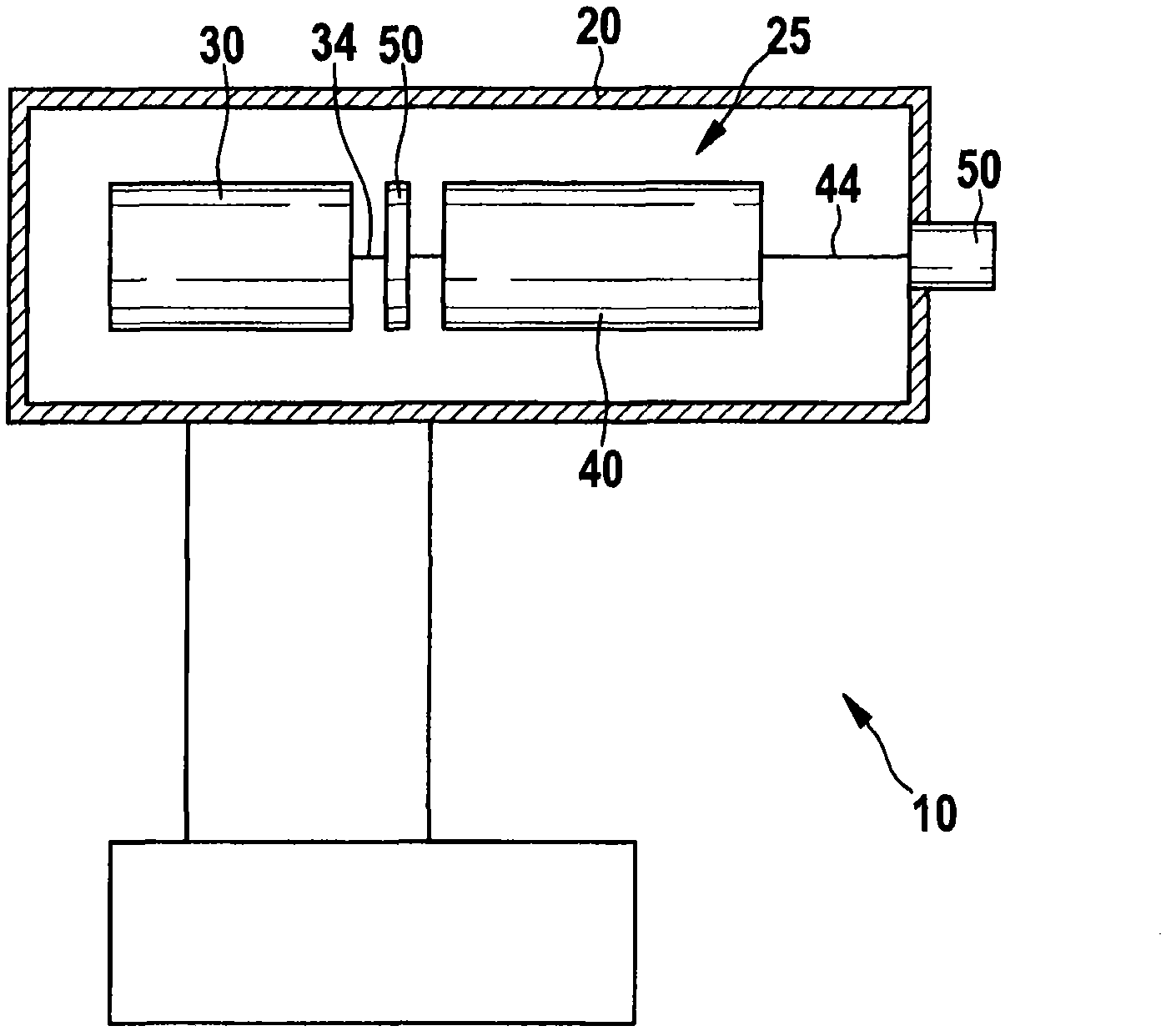
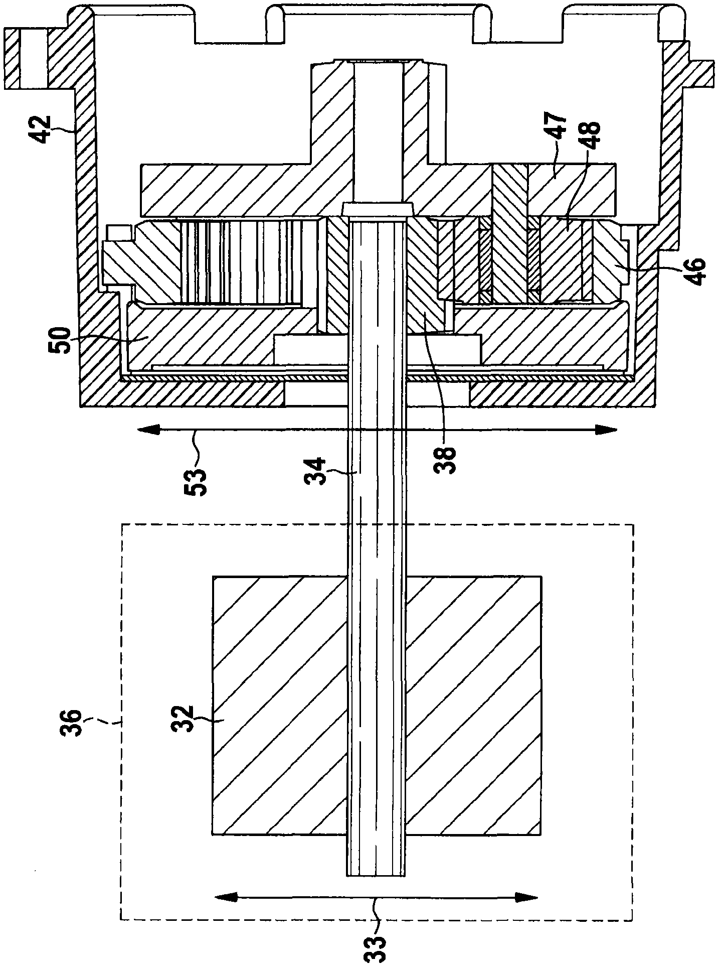
[0027] exist figure 1 A hand-held power tool 10 with a housing 20 according to the invention is schematically shown in FIG. Powertrain 25 includes motor 30 , transmission 40 and flywheel mass 50 . The motor 30 includes a rotor 32 (see figure 2 ) and the armature shaft, which serves as the drive shaft 34. Additionally, the power train 25 includes a tool receptacle 60 for receiving embedded tools, such as drill bits, screwdriver bits, and drill bits. Tool socket 60 is coupled to motor 30 via transmission 40 and output shaft 44 .

[0028]According to the invention, the hand-held power tool 10 has at least one flywheel mass 50 arranged rotationally symmetrically with respect to the drive shaft 34 , which is fixedly mounted on the drive shaft 34 so that the flywheel mass 50 is aligned with the drive shaft 34 Rotate at the same speed. according to figure 1 , the flywheel mass 50 is connected between the motor 30 and the transmission 40 . As an alternative, the flywheel mass ...


PUM


Abstract

The invention describes a hand-held power tool having a drive train (25), which includes a motor (30) with a rotor (32), a drive shaft (34), and a transmission (40). According to the invention, at least one flywheel mass (50) is provided that is positionable rotationally symmetrical to the drive shaft (34) and connectable to the drive shaft (34) for co-rotation therewith.

Description

technical field [0001] The invention relates to a hand-held power tool according to the preamble of claim 1 . Background technique [0002] In order to meet the demands for ever more compact and lightweight constructions in electric screwdrivers, electric drills and electric percussion drills, the drive train consisting of a series of motors, transmissions and tool sockets must be shortened length and reduce weight. However, this shortened and weight-reduced design should not lead to a reduction in the mechanical output of the hand-held power tool. On the contrary, despite the compact design, the output power should be as high as possible. [0003] A compact design of the hand-held power tool can be achieved, for example, by using a motor with a shorter and lighter design. However, this motor has the disadvantage that the moment of inertia is significantly reduced. In the case of work with hand-held power tools which is associated with a strong influence of dynamic effec...

Claims


Application Information

Patent Timeline
Patent Type & Authority Applications(China)
IPC IPC(8): B25F5/00
CPCB25F5/02B25B21/00B25F5/001
Inventor J·布伦嫩施图尔R·温德沙伊默H·勒姆
Owner ROBERT BOSCH GMBH
Learn More