Chassis structure of a motor vehicle body

An automobile body and automobile technology, which is applied in the direction of load-bearing body structure, substructure, superstructure, etc., can solve the problems of high production consumption and production cost, and achieve the effect of increasing torsional strength

Inactive Publication Date: 2011-06-29
GM GLOBAL TECH OPERATIONS LLC
View PDF7 Cites 15 Cited by
  • Summary
  • Abstract
  • Description
  • Claims
  • Application Information

AI Technical Summary

Problems solved by technology

[0011] Furthermore, it has been found to be disadvantageous in the prior art that a large number of individual structural parts and lining parts have to be connected individ

Method used


Image

  • Chassis structure of a motor vehicle body
  • Chassis structure of a motor vehicle body
  • Chassis structure of a motor vehicle body

Examples


Embodiment Construction

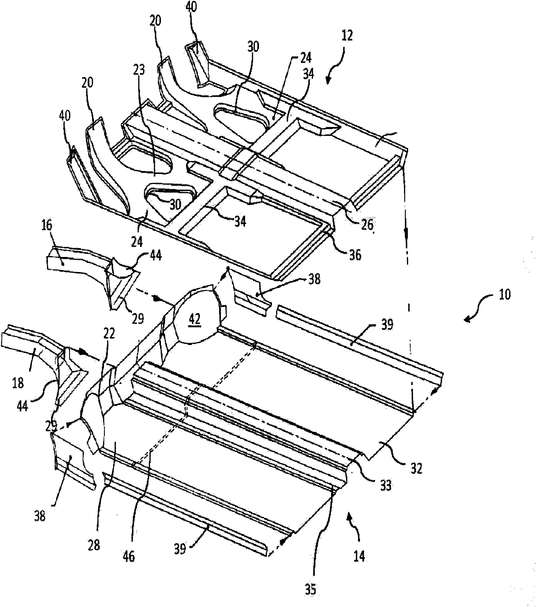
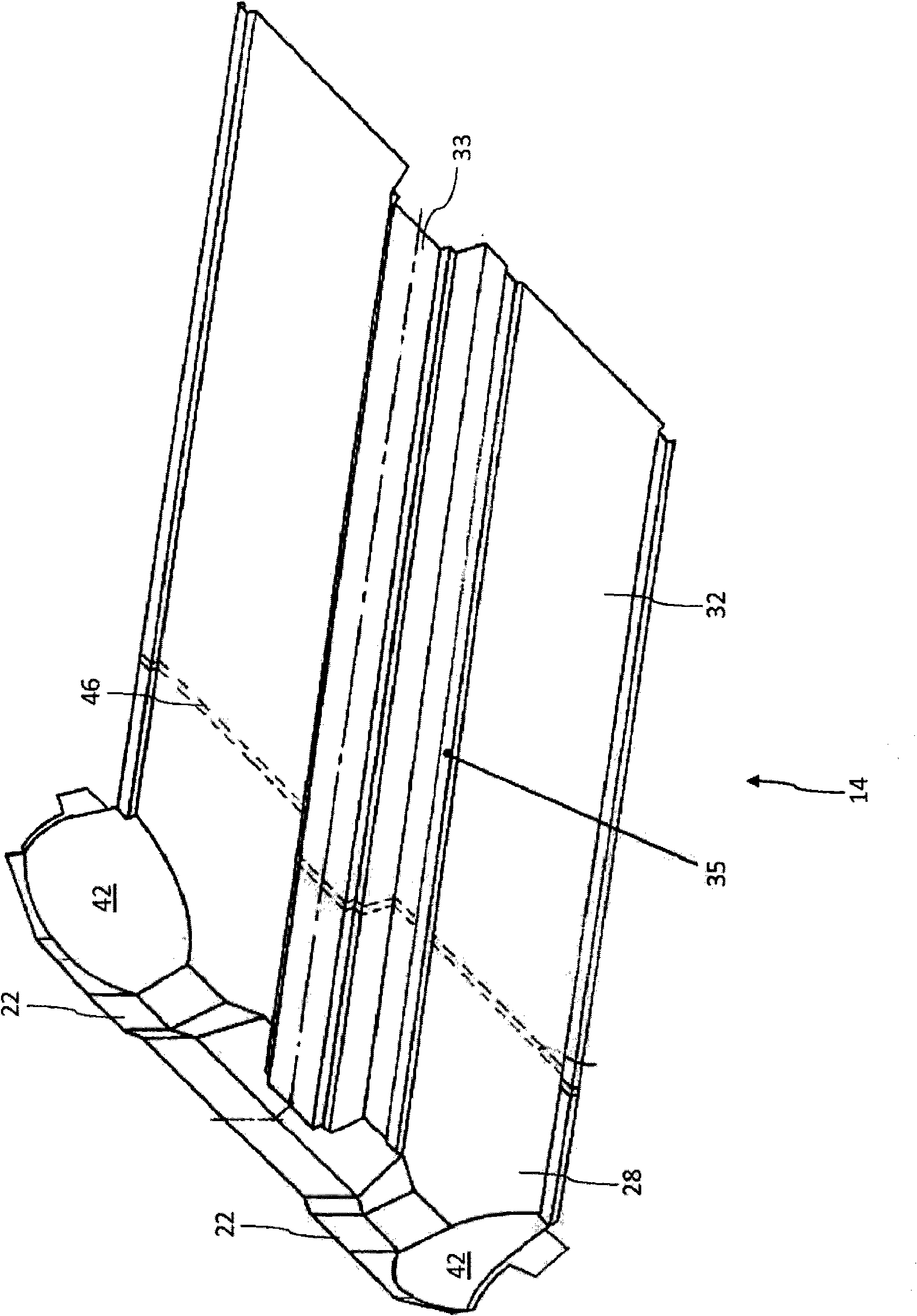
[0053] exist figure 1 Shown in the floor structure 10 of automobile body, this floor structure is at the front end, namely in press figure 1 In the illustration shown on the left, it adjoins the front frame 16 , 18 and at the rear end, that is to say on the right, adjoins the rear frame, usually a floor panel or a rear frame connection of the vehicle body. In this case, the floor structure 10 essentially consists of an inner load-bearing structure 12 , that is to say arranged in the dry area of ​​the vehicle body, and a floor 14 below which is connected to the load-bearing structure 12 .

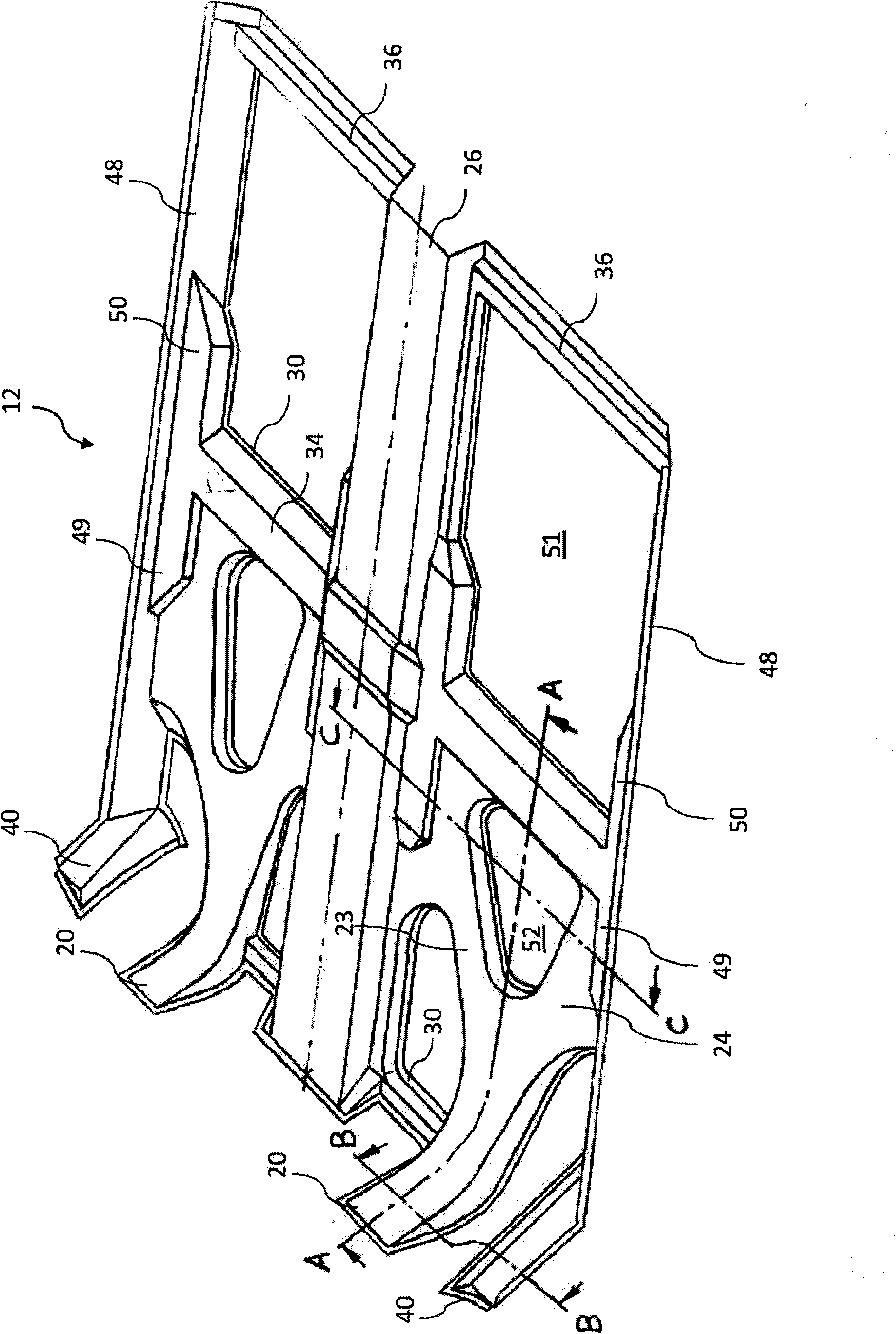
[0054] The inner carrier structure 12 has a plurality of interconnected or branched profile sections 20 , 23 , 24 , 26 , 34 , 40 . Almost all profile sections 20 , 23 , 24 , 26 , 34 , 40 are designed U-shaped in cross section and open downwards. The individual profile sections 20 , 23 , 24 , 26 , 34 , 40 are each welded to a flat section 28 , 32 of the base plate 14 lying below them with a...


PUM


Abstract

The present invention relates to a bearing structure arrangement of a motor vehicle body, which is provided with at least one bearing structure component (12) extending essentially in the longitudinal direction of the vehicle, which is provided in the interior or dry area of the motor vehicle to form a single-piece connection between the vehicle front wall and a rear frame of the body.

Description

technical field [0001] The invention relates to a load-bearing structure arrangement, in particular a floor structure of a motor vehicle body and in particular a motor vehicle or a base structure of a motor vehicle body arranged below a passenger compartment. Furthermore, the invention relates to a motor vehicle equipped with such a support structure arrangement. Background technique [0002] The load-bearing structural parts of the vehicle body, such as the front frame, the rear frame, the side members and the front and rear underbody, fulfill a static function on the one hand by absorbing the weight of the vehicle or individual vehicle components, such as engine components. On the other hand, at least some of these components have defined deformation properties in the event of extreme mechanical loading, for example in the event of a vehicle crash. [0003] The geometric design of the individual load-bearing structural parts of the vehicle body and their mechanical connec...

Claims


Application Information

Patent Timeline
IPC IPC(8): B62D25/20
CPCB62D25/2018B62D25/20B62D25/025B60K15/03B62D21/02B62D23/005B62D25/00
Inventor 托马斯·万克尤多·米尔德纳弗兰兹-约瑟夫·林格尔
Owner GM GLOBAL TECH OPERATIONS LLC
Why Eureka
Try Eureka