Profile arcing device

A technology for arc starters and profiles, which is applied in the field of profile processing and can solve problems such as troublesome use and inconvenient fixing

Pending Publication Date: 2022-07-12
安徽美沃智能门窗有限公司
View PDF0 Cites 0 Cited by
  • Summary
  • Abstract
  • Description
  • Claims
  • Application Information

AI Technical Summary

Problems solved by technology

[0005] The purpose of the present invention is to provide a profile arc starter to solve the defects that the existing profile arc starter is inconvenient to fix and troublesome to use

Method used


Image

  • Profile arcing device
  • Profile arcing device
  • Profile arcing device

Examples


Embodiment 1

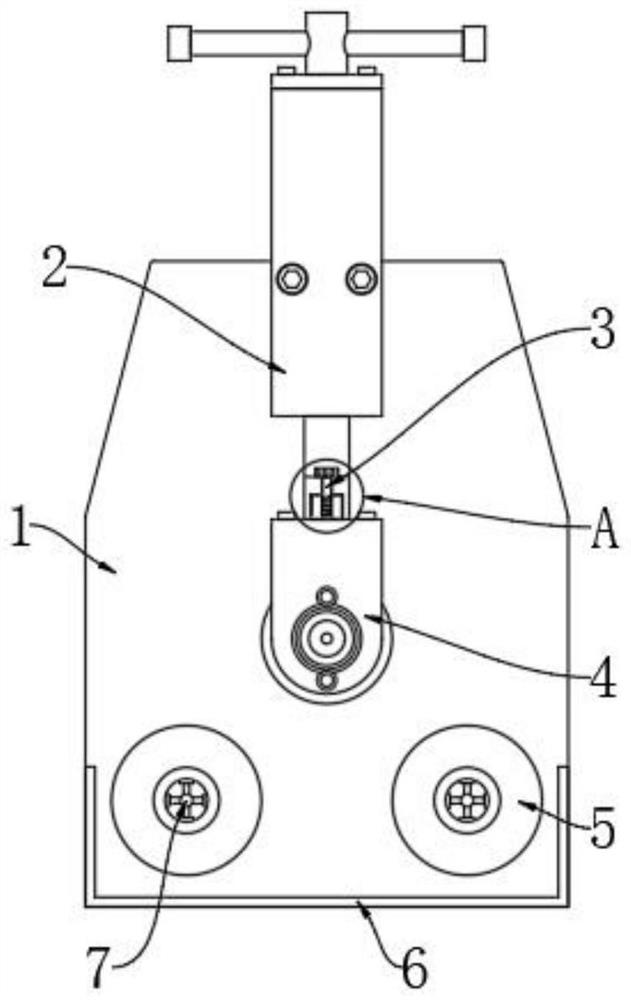
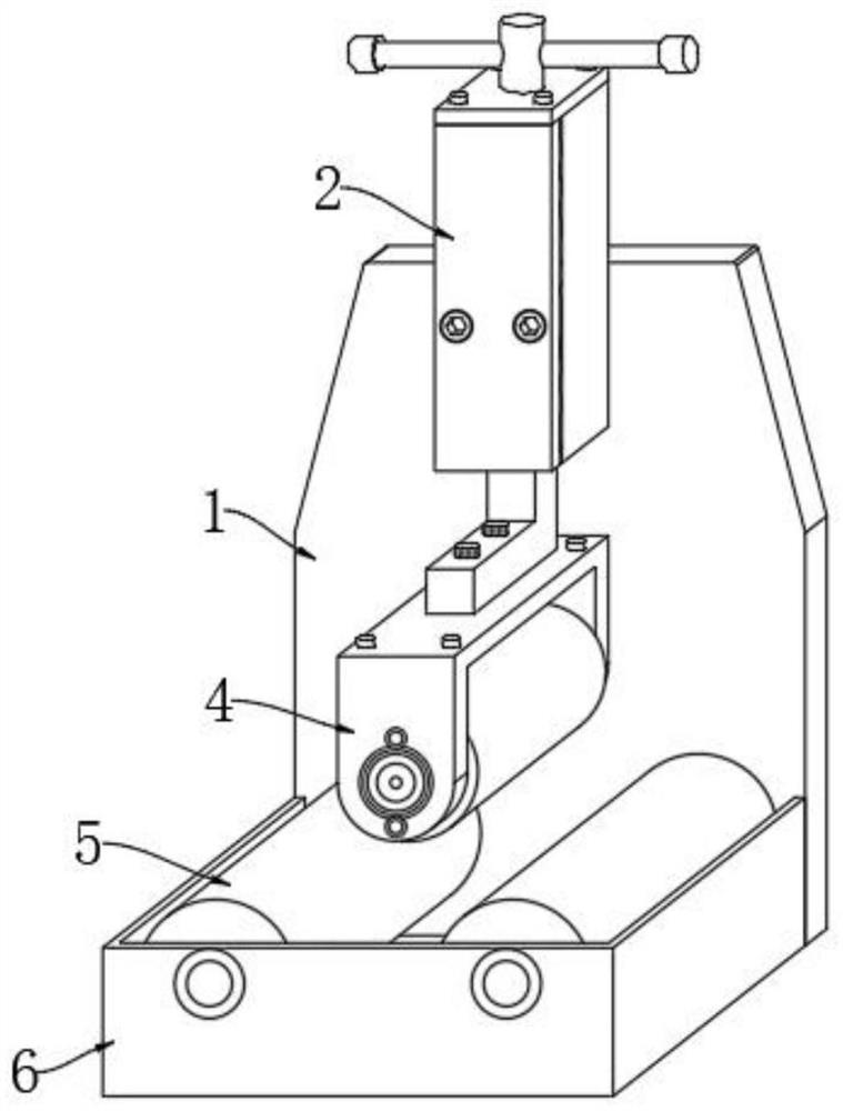
[0030] like figure 1 and Figure 4 As shown, when using this structure, first, the fixing structure 3 includes a fixing bolt 301, a clamping block 302 and a clamping slot 303, the clamping slot 303 is arranged at the bottom end of the inside of the lifting assembly 2, and the clamping block 302 is fixed to the top of the push wheel 4, The inside of the clamping block 302 is threadedly connected with a fixing bolt 301. The outer diameter of the clamping block 302 is smaller than the inner diameter of the clamping slot 303. A clamping structure is formed between the clamping block 302 and the clamping slot 303. Pick up the push wheel 4, and then remove the push wheel 4. The clamping block 302 at the top is aligned with the clamping slot 303, and then the push wheel 4 is pushed upward. At this time, the push wheel 4 pushes the clamping block 302 to insert into the interior of the clamping slot 303, and then the fixing bolt 301 is passed through the lifting assembly The inside of...

Embodiment 2

[0032] like figure 1 and Figure 5 As shown, when using this structure, first, the reinforcement structure 7 includes a reinforcement hole 701, a reinforcement rod 702 and a connecting rod 703, the reinforcement hole 701 is provided inside the arc starting roller 5, the reinforcement rod 702 is fixed inside the reinforcement hole 701, and A connecting rod 703 is fixed on one side of the reinforcing rod 702, and several reinforcing rods 702 are arranged. The several reinforcing rods 702 are distributed at equal intervals outside the connecting rod 703. The interior of the reinforced rods 702 can be connected by connecting rods 703 , and the structure formed between the reinforcing rods 702 and the connecting rods 703 can improve the internal strength of the arc starting roller 5 .

Embodiment 3

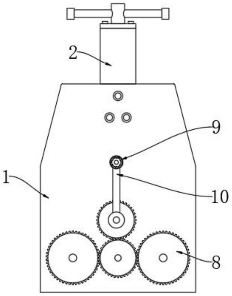
[0034] like image 3 and Image 6 As shown, when using this structure, first, the protective structure 9 includes a protective cover 901, an adaptive cotton 902, a fixing block 903 and a fixing groove 904. Self-adaptive cotton 902, a fixing block 903 is fixed inside the protective cover 901, a fixing groove 904 is arranged inside the rocker arm 10, and several fixing blocks 903 are arranged. The cover 901 can prevent the rocker arm 10 from slipping, and the adaptive cotton 902 inside the protective cover 901 can be automatically deformed according to the shape of the user's hand.


PUM


Abstract

The invention discloses a profile arcing device which comprises a plate body, a lifting assembly and an arcing roller, one end of the plate body is movably connected with a gear set, the bottom end of the plate body is fixedly provided with a fixing shell, the bottom end of one end of the plate body is movably connected with the arcing roller, the bottom end of the lifting assembly is provided with a push wheel, and the top end of the push wheel is provided with a fixing structure. And a reinforcing structure is arranged in the arcing roller. By arranging the fixing structure, the lifting assembly and the push wheel can be fixed, during use, the lifting assembly and the push wheel need to be fixed, at the moment, the push wheel is taken up, then a clamping block at the top end of the push wheel is aligned with a clamping groove, then the push wheel is pushed upwards, and at the moment, the push wheel pushes the clamping block to be inserted into the clamping groove; and then a fixing bolt penetrates through the lifting assembly and is screwed into the clamping block, at the moment, the lifting assembly and the push wheel can be fixed, guiding can be achieved through clamping between the clamping block and the clamping groove, and fixing between the lifting assembly and the push wheel is achieved.

Description

technical field [0001] The invention relates to the technical field of profile processing, in particular to a profile arc starter. Background technique [0002] With the continuous progress of society, the level of science and technology in our country is constantly improving. When the profile is used, a certain radian may be required. At this time, an arc starter will be required. The arc starter reaches the required arc, so a special type of profile arc starter is used; [0003] However, the existing profile arc starter on the market is inconvenient to fix and troublesome to use. Therefore, a profile arc starter has been developed to solve the above problems. SUMMARY OF THE INVENTION [0004] (1) Technical problems to be solved [0005] The purpose of the present invention is to provide a profile arc starter, which is used to solve the defects that the existing profile arc starter is inconvenient to fix and troublesome to use. (2) Content of the invention [0006] I...

Claims


Application Information

Patent Timeline
Patent Type & Authority Applications(China)
IPC IPC(8): B21D7/06B21D55/00
CPCB21D7/06B21D55/00
Inventor 洪长林唐家海周勤
Owner 安徽美沃智能门窗有限公司
Why Eureka
Try Eureka