Hydraulic pump control valve for construction machinery

A technology of construction machinery and hydraulic pumps, which is applied in the direction of mechanical equipment, earth movers/shovels, fluid pressure actuators, etc., can solve the problems of rising manufacturing costs and achieve the effect of size minimization

Inactive Publication Date: 2014-10-01
DOOSAN INFRACORE CO LTD
View PDF5 Cites 0 Cited by
  • Summary
  • Abstract
  • Description
  • Claims
  • Application Information

AI Technical Summary

Problems solved by technology

[0010] That is, in order to minimize the loss of power as described above, it is necessary to add many hydraulic components, so there is a problem that the manufacturing cost increases.

Method used


Image

  • Hydraulic pump control valve for construction machinery
  • Hydraulic pump control valve for construction machinery
  • Hydraulic pump control valve for construction machinery

Examples


Embodiment Construction

[0028] A valve for controlling a hydraulic pump of a construction machine according to an embodiment of the present invention will be described in detail below.

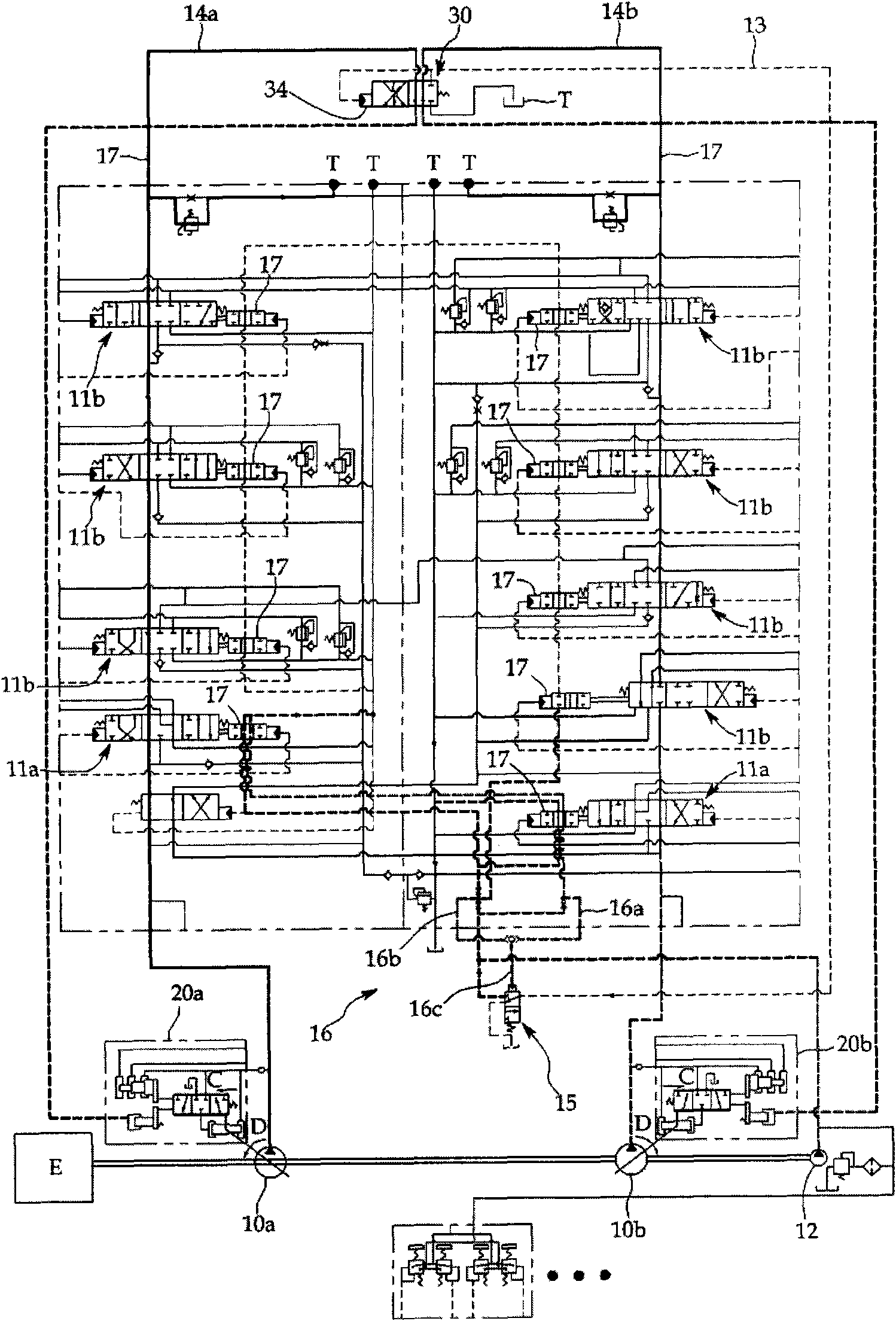
[0029] figure 2 It is a diagram schematically showing a hydraulic circuit to which the hydraulic pump control valve 30 is applied according to an embodiment of the present invention.

[0030] refer to figure 2 One side of the hydraulic pump control valve 30 is connected to the intermediate position bypass lines 14a, 14b and the control line 13, and the other side is connected to the oil tank T and the first and second regulators 20a, 20b. On the other hand, the control line 13 is connected to the pressure receiving portion 34 of the hydraulic pump control valve 30 .

[0031] With the structure as described above, if the hydraulic pump control valve 30 is switched to figure 2 state (hereinafter referred to as "second position"), the pressure of the intermediate position bypass line 14a, 14b is transmitted to the...


PUM


Abstract

The invention relates to a valve for controlling hydraulic pumps of construction machinery, which is characterized in that the valve comprises a main valve body (42); a first and a second inlets (32a, 32b) formed on the main valve body and connected to a first and a second neutral-position bypass pipelines (14a, 14b) respectively; a first and a second outlets (33a, 33b) disposed on the main valve body and connected to each of adjusters (20a, 20b); a third outlet (33c) disposed on the main valve body and connected to a oil tank (T); and a slide valve (35) which is disposed on the main valve body, allowed to move between the first position and the second position, and provided with a first and a second grooves separated from each other. If the slide valve is moved to the first position, each of the first and the second inlets is connected to the third outlet by the first and the second grooves; and if the slide valve is moved to the second position, the first and the second inlets are connected to the first and the second outlets respectively.

Description

technical field [0001] The present invention relates to construction machinery such as excavators, and more particularly to a hydraulic pump control valve for construction machinery for selecting one of a pressure in a bypass line at an intermediate position and a control pressure as a signal pressure for controlling a hydraulic pump of the construction machinery (VALVE FOR CONTROLLING HYDRAULIC PUMPOF CONSTRUCTION MACHINERY). Background technique [0002] Generally speaking, a construction machine such as an excavator is equipped with a plurality of actuators for running or driving various working devices. driven by oil. [0003] In order to minimize the loss of power, the flow rate of hydraulic oil discharged from the above-mentioned variable displacement hydraulic pump is controlled according to the working load, an example of which is shown in figure 1 middle. [0004] refer to figure 1 , a pair of hydraulic pumps 1 driven in series on the engine adjust the swash pla...

Claims


Application Information

Patent Timeline
Patent Type & Authority Patents(China)
IPC IPC(8): F15B13/02
CPCE02F9/22F15B13/043F15C3/02
Inventor 安玄植
Owner DOOSAN INFRACORE CO LTD
Why Eureka
Try Eureka