Lightning protection circuit

A lightning protection circuit and lightning protection technology, applied in the field of communication, can solve the problems of high protection level, can not reach, can not guarantee the reliable operation of equipment, etc., achieve high-standard lightning protection, reduce the number of effects

Active Publication Date: 2014-06-04
HUAWEI MACHINERY
View PDF2 Cites 0 Cited by
  • Summary
  • Abstract
  • Description
  • Claims
  • Application Information

AI Technical Summary

Problems solved by technology

However, this technology has two disadvantages: 1. A large number of protective devices must be added to each port, and the packages of these protective devices are very large. When there are many ports, a large number of printed circuit boards (PCB, Printed Circuit Board) must be required ) space, which contradicts the development of PSE equipment towards miniaturization (ports are becoming more and more dense, and PCB layout and wiring are becoming more and more compact), which makes it difficult for this solution to be widely used on PSE equipment with high-density POE ports Application; 2. The (1.2) and (3.6) lines of the network port in the figure do not add protective devices, and are protected by isolation, while the (4.5) and (7.8) lines are equipped with protective devices. When the network port induces a surge overvoltage , (4.5), (7.8) line protection device action, the surge voltage is pulled down, and (1.2), (3.6) line is still in a high voltage state, a breakdown may occur between the high voltage and low voltage, and the protection is also It cannot reach a higher level of protection, and cannot guarantee the reliable operation of the equipment in actual use

Method used


Image

  • Lightning protection circuit
  • Lightning protection circuit
  • Lightning protection circuit

Examples


Embodiment 1

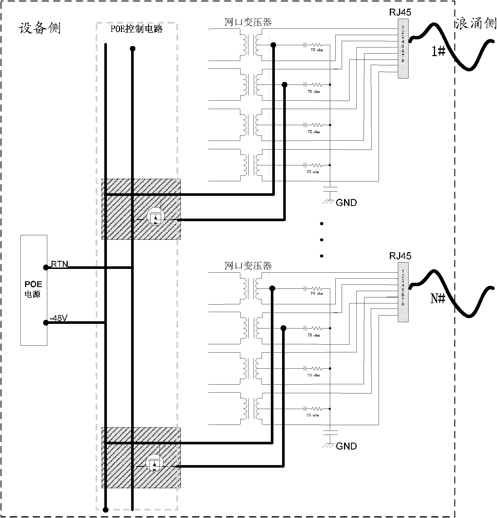
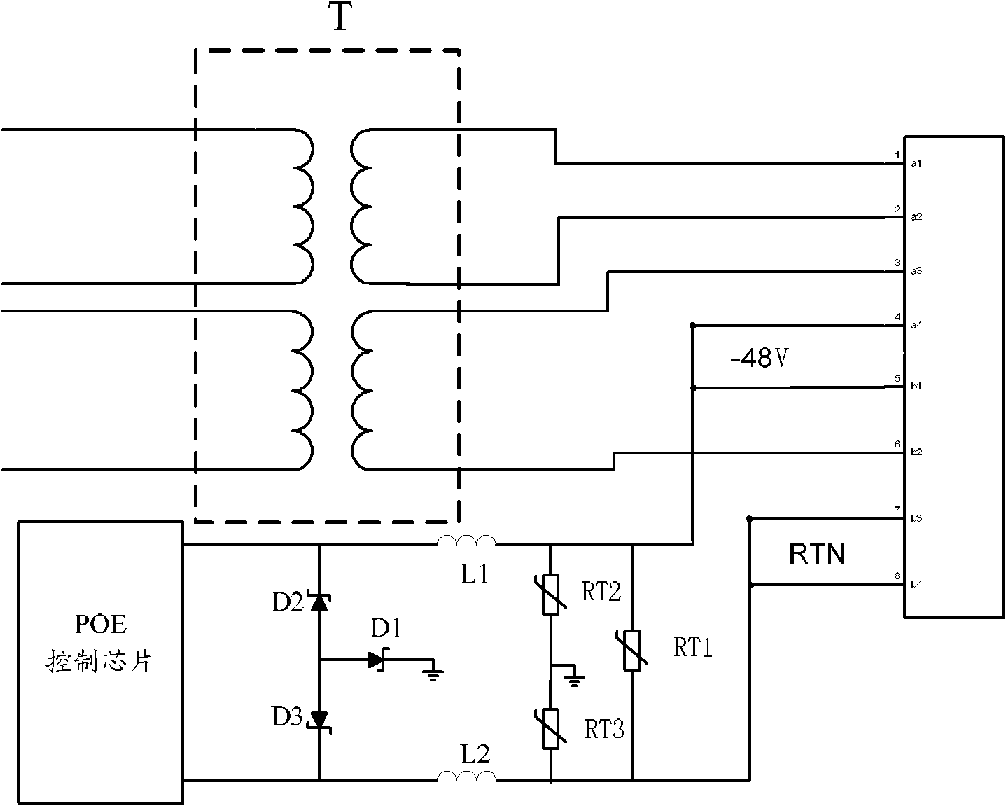
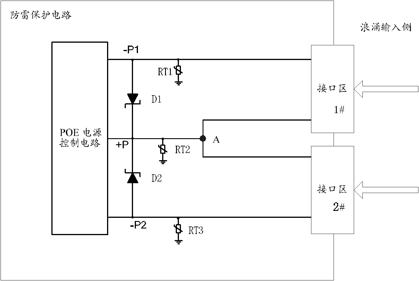
[0031] A lightning protection circuit provided by an embodiment of the present invention specifically includes: a lightning protection device used to protect a PoE port from being damaged by a surge overvoltage. The lightning protection device includes: a first common mode protection device, a second common mode A mode protection device and a differential mode protection device, the first common mode protection device is connected between the first power supply output line and the common end, or the first common mode protection device is connected between the first power supply input line and the common end, wherein , the first power supply output line is a shared power supply line connected to the first output end of the PoE power supply control circuit and the interface area, and the first power supply input line is a power supply line connected to the first input end of the PoE power supply control circuit and the PoE power supply; The two common mode protection devices are ...

Embodiment 2

[0040] A lightning protection circuit provided by an embodiment of the present invention specifically includes: a lightning protection device used to protect a PoE port from being damaged by a surge overvoltage. The lightning protection device includes: a first common mode protection device, a second common mode A mode protection device and a differential mode protection device, wherein the first common mode protection device is connected between the first power input line and the common end, or the first common mode protection device is connected between the first power output line and the common end , the first power supply input line is a power supply line connected to the first input terminal of the PoE power supply control circuit and the PoE power supply, and the first power supply output line is a shared power supply line connected to the first output terminal of the PoE power supply control circuit and the interface area; The two common mode protection devices are conne...


PUM


Abstract

A lightning protection circuit comprises a lightning protection device. The lightning protection device comprises a first common mode protecting device (RT2), a second common mode protecting device (RT1, RT3) and a differential mode protecting device (D1, D2). The first common mode protecting device (RT2) is connected between a first power supply output lead (+P) and a common port or between a first power supply input lead and the common port, wherein the first power supply output lead (+P) is a common supply lead connected between a first output port of a Power over Ethernet (PoE) power supply control circuit and an interface region, and the first power supply input lead is a supply lead connected between a first input port of the PoE power supply control circuit and a PoE power supply. The second common mode protecting device (RT1, RT3) is connected between a second power supply output lead (-P1, -P2) and a common port or between a second power supply input lead and the common port or between the first power supply input lead and the second power supply input lead, wherein the second power supply output lead (-P1, -P2) is a supply lead connected between a second output port of the PoE power supply control circuit and the interface region, and the second power supply input lead is a supply lead connected between the second input port of the PoE power supply control circuit and the PoE power supply. The differential mode protecting device (D1, D2) is connected between the first power supply output lead (+P) and the second power supply output lead (-P1, -P2). The lightning protection circuit reduces the number of protecting devices, saves PCB space and decreases the design cost for PoE ports. In addition, as all of the interface regions are connected to the common ports via protecting devices, a relatively large amount of surge energy can be released, achieving a high level of lightning protection.

Description

technical field [0001] The invention relates to the technical field of communication, in particular to a lightning protection circuit. Background technique [0002] Power over Ethernet (PoE, Power over Ethernet) refers to the transmission of data signals for some terminals based on the interconnection protocol (IP, Internet Protocol) between networks on the existing Ethernet Cat. At the same time, it can also provide DC power technology for such devices. PoE technology uses a common Ethernet cable to transmit Ethernet signals and DC power at the same time, and integrates power and data in the same cable for transmission. PoE technology can be used for Various network terminals, such as: IP phones, wireless access points, portable device chargers, credit card machines, cameras, data acquisition equipment, etc. provide reliable and centralized power supply. Network terminals do not need an external power supply, only one network cable is connected It can work normally, and ba...

Claims


Application Information

Patent Timeline
Patent Type & Authority Patents(China)
IPC IPC(8): H02H9/04H02H9/06
CPCH02H9/042
Inventor 朱跃生王玮峰戴养哩
Owner HUAWEI MACHINERY
Why Eureka
Try Eureka