
Motor

A motor and shaft tube technology is applied in the field of motors that can prevent the shaft tube from being deformed, and can solve the problem that the stator is prone to excessive pressure on the shaft tube and the like

Active Publication Date: 2011-06-29
SUNONWEALTH ELECTRIC MACHINE IND
View PDF3 Cites 3 Cited by
  • Summary
  • Abstract
  • Description
  • Claims
  • Application Information

AI Technical Summary

Problems solved by technology

[0008] The purpose of the present invention is to provide a motor to solve the problem that the stator of the existing motor tends to excessively compress the shaft tube during assembly

Method used


Image

  • Motor
  • Motor
  • Motor

Examples


Embodiment approach

[0051] Please refer to Figure 4 , 5 Shown in and 6 is the first embodiment of the tight fitting portion 4 and the adjustment gap 5 . Wherein the tight fit portion 4 can be at least one protrusion (such as a convex rib, a bump or other structural design with the same function) formed on the inner wall of the assembly hole 21, and the shaft tube 11 has an outer diameter in the radial direction. Tube diameter D, with the help of the design of the at least one protrusion, the minimum diameter of the assembly hole 21 is smaller than the outer tube diameter D of the shaft tube 11, so that the stator group 2 can be more tightly combined with the outer peripheral wall of the shaft tube 11 111; In addition, in this embodiment, the convex part is designed as a convex rib 211, and there are two convex ribs 211 (only one can be selected according to requirements), and the two convex ribs 211 can axially extend to the assembly hole 21 The inner hole wall of the rib 211 abuts against the...


PUM


Abstract

The invention provides a motor which at least comprises a base, a stator assembly and a rotor, wherein the base is provided with a shaft tube, and the shaft tube is provided with a peripheral wall; the stator assembly is combined with the shaft tube of the base and is provided with an assembling hole, a plurality of close fit parts are formed between the inner side hole wall of the assembling hole and the peripheral wall of the shaft tube, and an adjusting gap is respectively arranged between the close fit parts; and the rotor is provided with a central shaft which is rotatably combined with the shaft tube of the base. By means of the simple structural design of the adjusting gap, the problem that the shaft tube has high possibility of being excessively oppressed by the stator assembly issolved.

Description

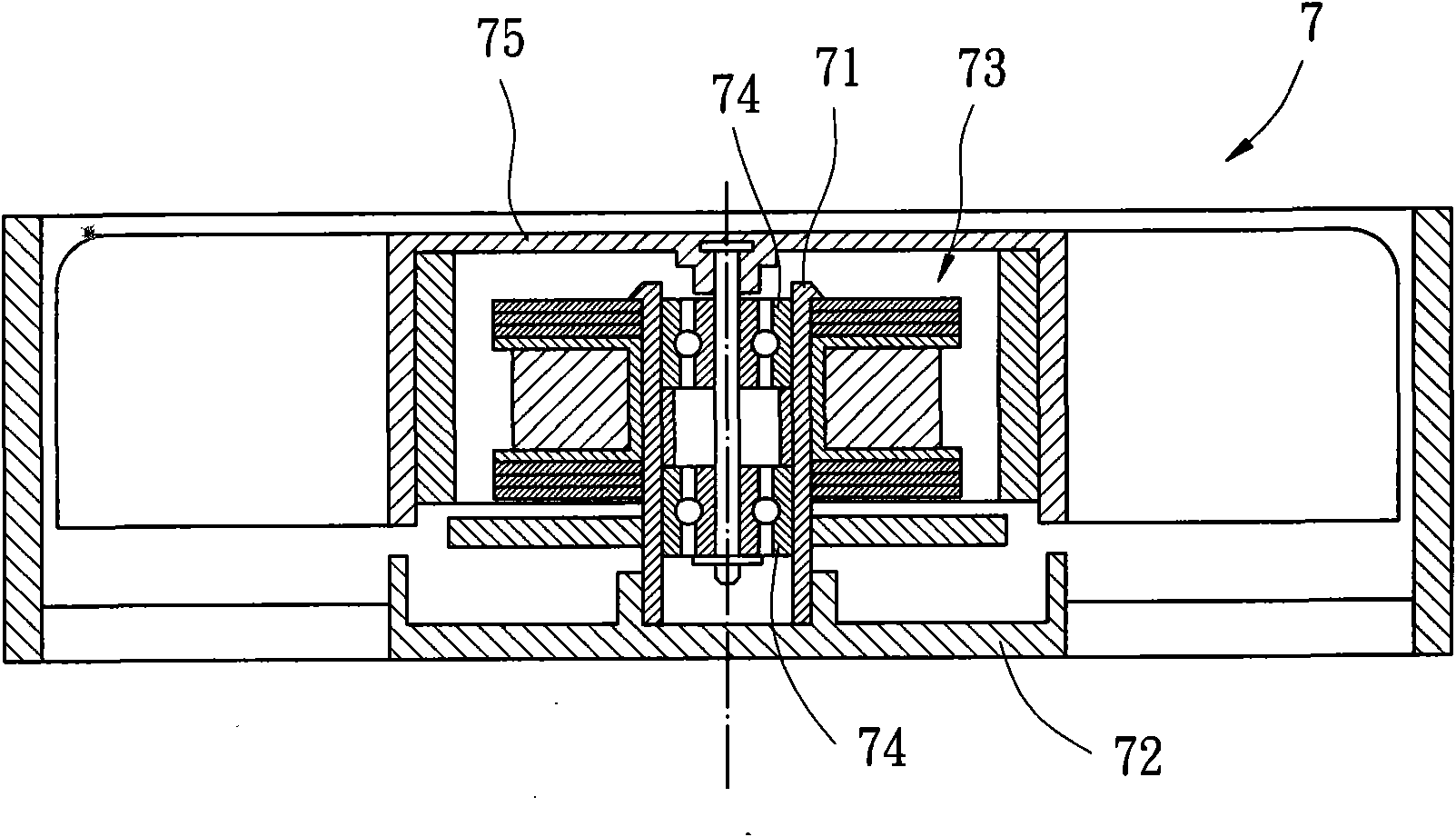
technical field [0001] The invention relates to a motor, especially a motor capable of preventing deformation of a shaft tube. Background technique [0002] Existing motors that are common in the market can be roughly divided into motors with metal shaft tubes and motors with plastic shaft tubes. [0003] Please refer to figure 1 As shown, for example, the Taiwan Patent No. 384947 "Metal Tube and Bearing Structure of Radiating Fan Motor" discloses a motor with a metal shaft tube. The existing motor 7 combines a metal shaft tube 71 with a shell seat 72, and has a stator seat 73 tightly fitted on the outer peripheral wall of the metal shaft tube 71; in addition, several bearings are arranged in the metal shaft tube 71 74, the several bearings 74 can be pivotally connected to a rotor 75. [0004] However, in the actual assembly process, the stator base 73 is generally combined with the outer peripheral wall of the metal shaft tube 71 in a tight fit, it is only assumed that t...

Claims


Application Information

Patent Timeline
Patent Type & Authority Applications(China)
IPC IPC(8): H02K1/18H02K7/08H02K15/14
Inventor 洪银树
Owner SUNONWEALTH ELECTRIC MACHINE IND
Learn More