
Movable ankle baseboard

A foot plate and ankle foot technology, applied in the field of moving ankle foot plate, can solve the problems of stiffness, discomfort in wearing of amputee patients, easy loosening of the moving ankle foot plate and the shell, etc., to increase strength and flexibility, increase comfort, and increase flexibility. Effect

Inactive Publication Date: 2013-03-13
英中耐(福建)假肢矫形器集团有限公司
View PDF4 Cites 0 Cited by
  • Summary
  • Abstract
  • Description
  • Claims
  • Application Information

AI Technical Summary

Problems solved by technology

[0002] The current structure of the movable ankle and foot plate is as follows: figure 1 , figure 2 As shown, the foot plate is made of wooden material. When making artificial feet, the shell is directly injected outside the wooden movable ankle plate (or the shrinkage rate of the movable ankle plate made of different materials is different from that of the shell). Once the movable ankle plate shrinks, the dynamic The connection between the ankle-foot plate and the shell is easy to loosen, causing discomfort to the amputee, and it is made up of the movable ankle-foot keel 1 and the forefoot shrapnel 4. The corresponding forefoot shrapnel 4 is also a whole piece, which is very stiff and cannot meet the deformation requirements of normal gait, which affects the walking ability of the user

Method used


Image

  • Movable ankle baseboard
  • Movable ankle baseboard
  • Movable ankle baseboard

Examples


Embodiment Construction

[0022] The present invention will be described in detail below in conjunction with the drawings, so that those skilled in the art can better understand the present invention. It is possible to modify, add and replace the following embodiments without exceeding the protection scope of the present invention.

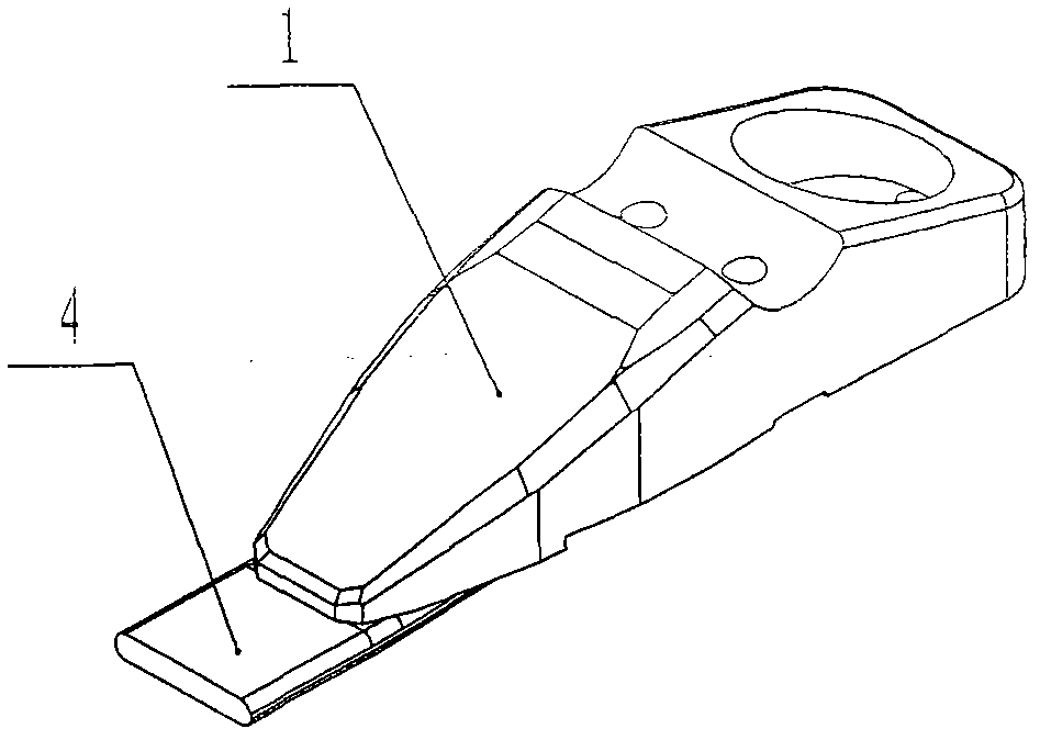
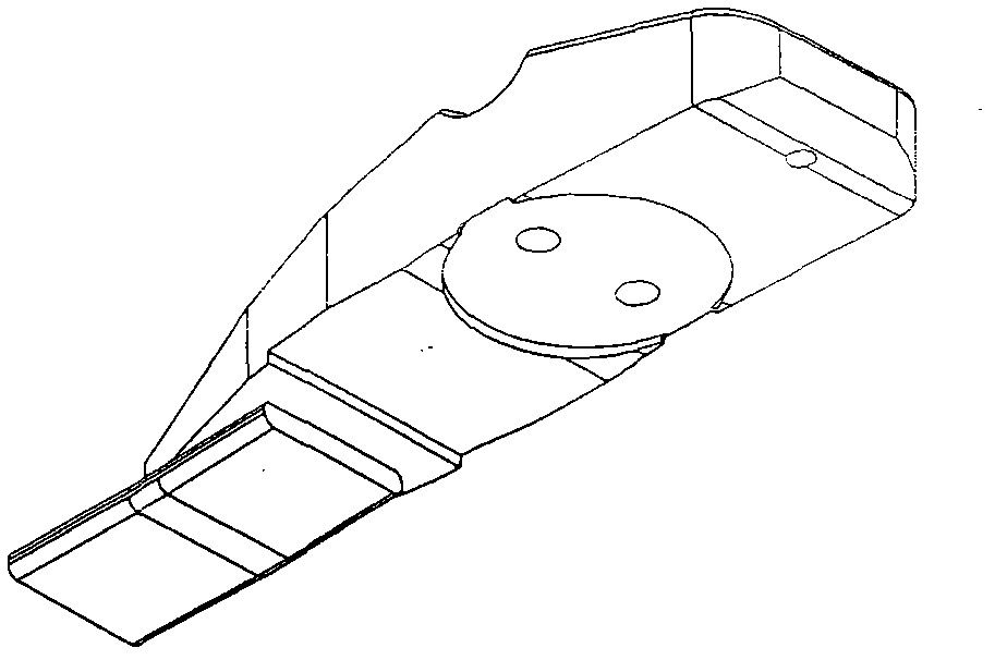
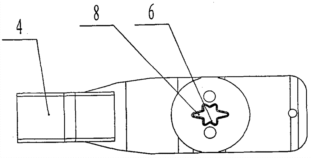
[0023] like image 3 As shown, a movable ankle foot plate is composed of a movable ankle keel 1 and a forefoot shrapnel 4. There is a connecting hole 6 located in the middle of the foot center at the bottom of the movable ankle keel 1, and there are shallow grooves 8 on the front and rear sides of the connecting hole 6. , the depth and width of the connection hole 6 are greater than the shallow groove 8, and the inner angle of the connection hole 6 is an acute angle, which is star-shaped in this example, and can also be radial.

[0024] like Figure 4 , Figure 5 , Image 6 , shown in Fig. 7, Fig. 8, a kind of wooden double-hole movable ankle foot plate is made up of do...


PUM


Abstract

The invention belongs to artificial limb, and particularly relates to a movable ankle baseboard which comprises a movable ankle keel and a half sole elastic piece, and has the structural key points that: a connecting hole is arranged at the bottom of the movable ankle keel, shallow slots are arranged at the front side and the rear side of the connecting hole, and the connecting hole is deeper than the shallow slots. In the invention, the connecting hole is additionally arranged at the bottom of the movable ankle keel, mutual wrapping is formed between the baseboard and an injection-molded shell, and the inner angle of the connecting hole is an acute angle and has a wedge-shape structure after the connecting hole is poured, so that the baseboard and the shell are closely connected; and due to the unique separate sole structure and a hollow design, the ankle baseboard has certain elasticity and deforms when people walk so as to accord with the deformation requirement of normal tread and enable a patient to adapt to different pavement requirements; in addition, the unique U-shaped half sole elastic piece can store proper energy.

Description

technical field [0001] The invention belongs to artificial limbs, in particular to movable ankle and foot plates. Background technique [0002] The current structure of the movable ankle and foot plate is as follows: figure 1 , figure 2 As shown, the foot plate is made of wooden materials. When making artificial feet, the shell is directly injected outside the wooden movable ankle plate (or the shrinkage rate of the movable ankle plate made of different materials is different from that of the shell). Once the movable ankle plate shrinks, the dynamic The connection between the ankle-foot plate and the shell is easy to loosen, causing the amputee to wear uncomfortable, and it is composed of the movable ankle-foot keel 1 and the forefoot shrapnel 4, the movable ankle-foot keel 1 is an integral shape, and the movable ankle-foot keel 1 The corresponding forefoot shrapnel 4 is also a whole piece, which is very stiff and cannot meet the deformation requirements of normal gait, w...

Claims


Application Information

Patent Timeline
Patent Type & Authority Patents(China)
IPC IPC(8): A61F2/66
Inventor 陈仁建林思成林舒
Owner 英中耐(福建)假肢矫形器集团有限公司
Learn More