Planar module type equipment structure

A flat module and equipment technology, which is applied in the direction of surface pretreatment, devices for coating liquid on the surface, electrical components, etc., can solve problems such as affecting the working speed, etc., and achieve the effect of compact layout, simple and fast delivery

Inactive Publication Date: 2011-07-06
SHENYANG KINGSEMI CO LTD
View PDF5 Cites 2 Cited by
  • Summary
  • Abstract
  • Description
  • Claims
  • Application Information

AI Technical Summary

Problems solved by technology

The traditional linear TRACK (gluing, developing and cleaning equipment) system will avoid interference when the manipulator cooperates with other units, which will affect the working speed

Method used


Image

  • Planar module type equipment structure
  • Planar module type equipment structure
  • Planar module type equipment structure

Examples


Embodiment Construction

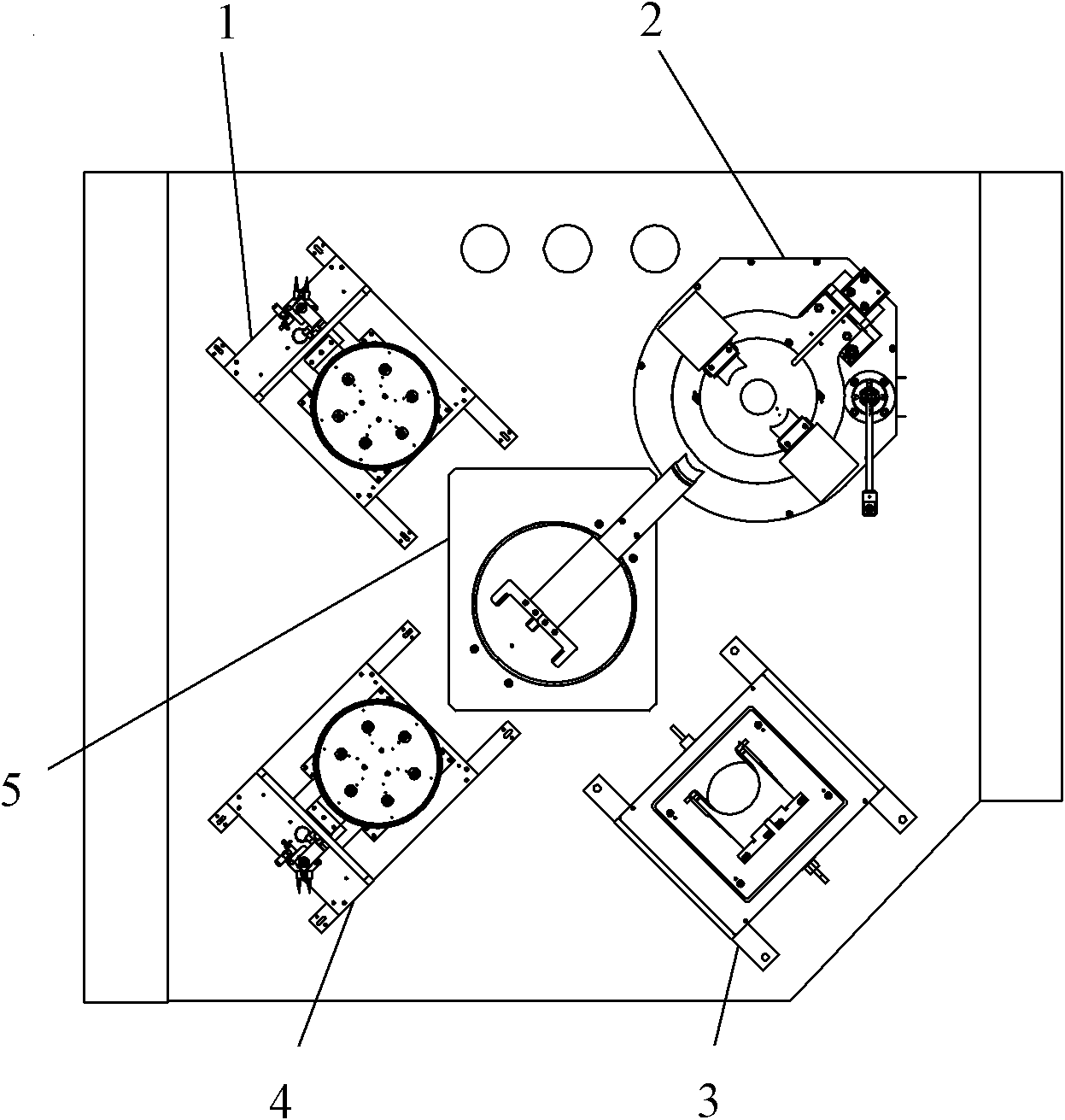
[0015] Such as Figure 1-Figure 2 As shown, the planar modular equipment structure of the present invention mainly includes: hot plate I 1, process module 2, film cassette 3, hot plate II 4, two-axis manipulator 5, slide table 6, base 7, etc., the specific structure is as follows:

[0016] Two-axis manipulator 5 is in the center, hot plate I 1, process module 2, film cassette 3, and heat plate II 4 are distributed around the two-axis manipulator 5, heat plate I 1, process module 2, film box 3, and heat plate II 4 1. The two-axis manipulator 5 is located on the same plane, and the two-axis manipulator 5 only has rotation and telescopic actions, without lifting. The transfer of wafers among the modules is realized by the scheduling of the two-axis manipulator 5 in the center.

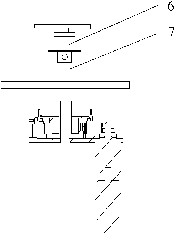
[0017] The telescopic part of the two-axis manipulator 5 is provided with a slide table 6 and a base 7, and the two-axis manipulator 5 is driven by the slide table 6 connected on the base 7 to realize th...


PUM


Abstract

The invention relates to the field of spin coating of semiconductors, in particular to a planar module type equipment structure which is applied to spin coating equipment for the wafer coating process in the manufacture procedure of semiconductors. The equipment structure is provided with a hot disk I, a process module, a wafer box, a hot disk II and a dual-shaft manipulator which are positioned in the same plane, wherein the dual-shaft manipulator is arranged in the center, and the hot disk I, the process module, the wafer box and the hot disk II are distributed around the dual-shaft manipulator. The manipulator of the traditional compact structure can move in the X, Y and T three axes for picking and placing wafers in different positions and with different heights. All the process units of the structure provided by the invention are in the same plane and have no reference to movement in the Y axis. The manipulator rotates in the center and picks and places wafers easily and quickly by telescoping fingers.

Description

technical field [0001] The invention relates to the field of semiconductor compounding, in particular to a planar modular equipment structure, which is applied to the compounding equipment in the wafer coating process in the semiconductor manufacturing process. Background technique [0002] The traditional compact structure is that the manipulator can move in X, Y, and T axes to pick and place wafers at different positions and heights. The traditional linear TRACK (gluing, developing and cleaning equipment) system will avoid interference when the manipulator cooperates with other units, which will affect the working speed. Contents of the invention [0003] The purpose of the present invention is to provide a planar modular equipment structure, which can shorten the walking path of the manipulator to other units and shorten the motion track. [0004] Technical scheme of the present invention is: [0005] A planar modular equipment structure, the equipment structure is pr...

Claims


Application Information

Patent Timeline
Patent Type & Authority Applications(China)
IPC IPC(8): B05C5/00B05C13/02B05D3/00H01L21/00H01L21/67
Inventor 侯宪华孙东丰
Owner SHENYANG KINGSEMI CO LTD
Why Eureka
Try Eureka