
Temporary supporting device for roadway drifting

A temporary support and roadway technology, applied in mine roof support, mining equipment, earthwork drilling and mining, etc., can solve the problems of time-consuming, laborious, unsafe, unable to adapt to the change of roadway roof, etc., and achieve the effect of simple and flexible structure

Inactive Publication Date: 2011-07-06
HUNAN UNIV OF SCI & TECH
View PDF4 Cites 31 Cited by
  • Summary
  • Abstract
  • Description
  • Claims
  • Application Information

AI Technical Summary

Problems solved by technology

Among them, the airborne front beam type is fixed on the roadheader and is used in conjunction with the roadheader. It cannot be used for blasting and excavating roadways, and the shape of the support surface of the top beam is fixed, which cannot adapt to changes in the roof of the roadway; Before permanent support, a single hydraulic prop or wooden column is used to match the top beam, and the shed is manually erected in the empty roof area of ​​the roadway, which is time-consuming and laborious, and is not safe yet; the suspended type is based on the permanent support equipment installed in the roadway. Suspend multiple front probe beams on the installed permanent support equipment, and extend longitudinally along the roadway to the empty roof area, and play a role in protecting the roof of the empty roof area. There is no initial support force, poor reliability, and personnel Working in the empty top area, the safety is poor

Method used


Image

  • Temporary supporting device for roadway drifting
  • Temporary supporting device for roadway drifting
  • Temporary supporting device for roadway drifting

Examples


Embodiment Construction

[0013] The present invention will be described in further detail below in conjunction with the accompanying drawings and embodiments.

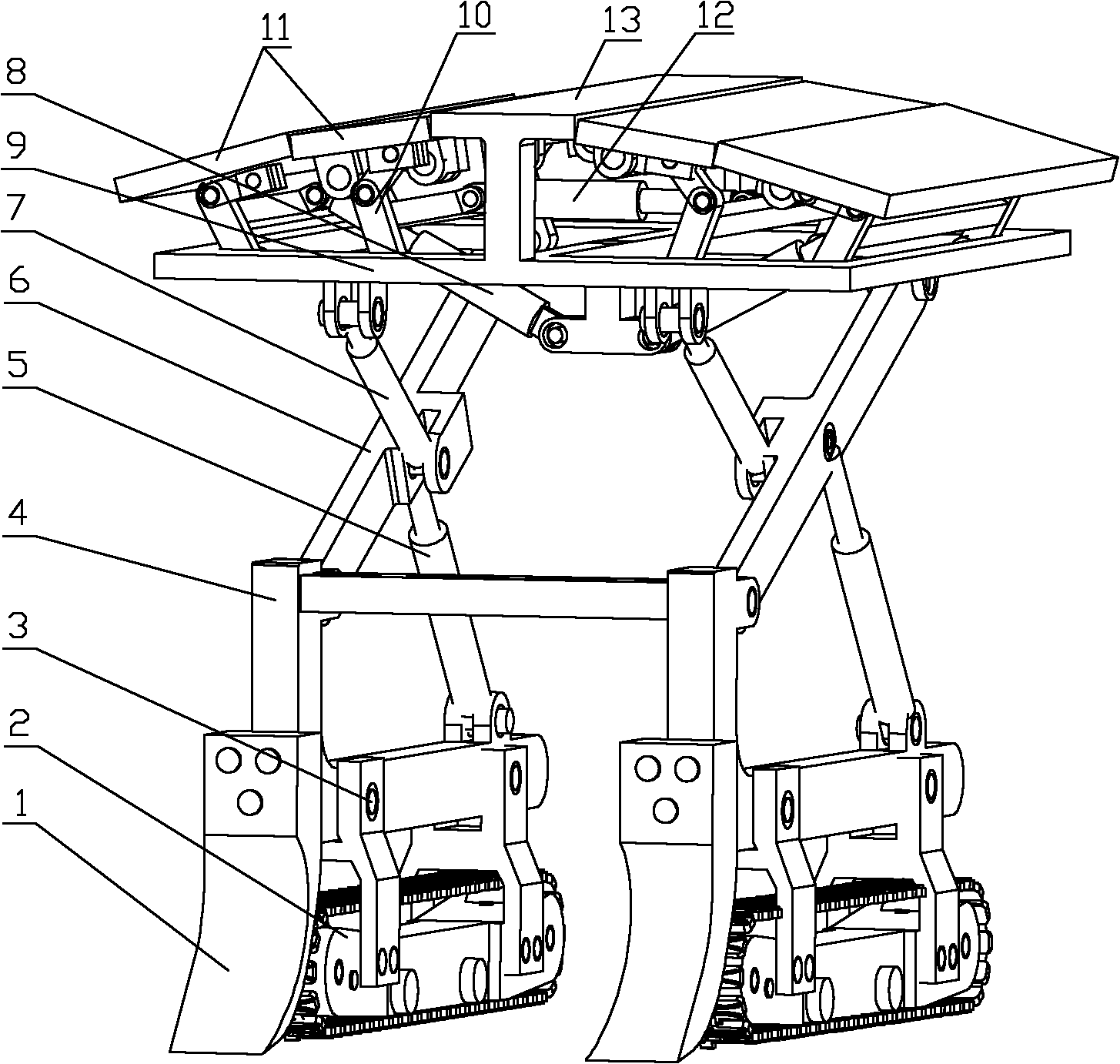
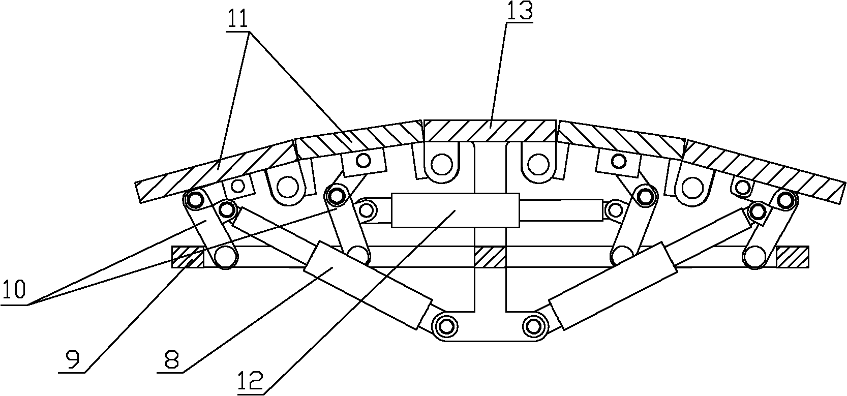
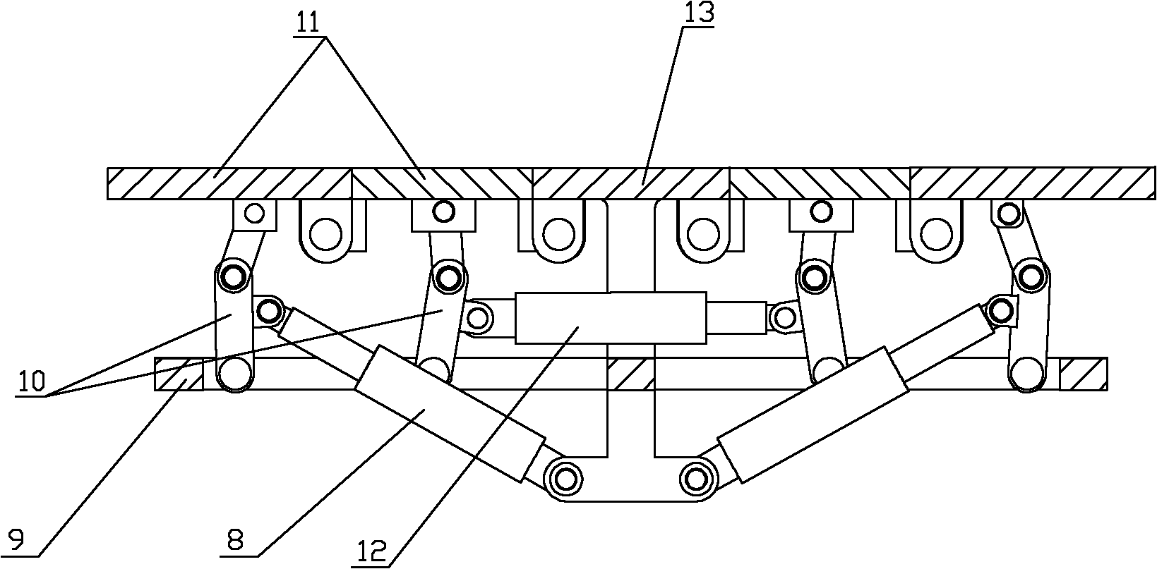
[0014] see figure 1 , figure 2 , image 3 and Figure 4 , in this embodiment, the upper end of the vertical beam in the middle of the front and rear beams of the top beam frame 9 is fixedly connected with the support middle plate 13, and the left and right sides of the support middle plate 13 are respectively provided with two support side plates 11, and the support Between the middle protection plate 13 and the support side plate 11 and between each support side plate, the lower side is hinged. The lower front and rear ends of the support side plate 11 are provided with a link mechanism 10, and the link mechanism 10 is hinged with the front and rear beams of the top beam frame 9. The left and right ends of the bottom of the vertical beam below the middle part of the top beam frame 9 are respectively hinged with a slant brace oil cylinder...


PUM


Abstract

The invention relates to a temporary supporting device for roadway drifting. The key technical points of the temporary supporting device for roadway drifting are as follows: a middle support plate is fixedly connected with the upper part of a top beam frame; two side support plates are respectively arranged at two sides of the middle support plate; the support plates are mutually hinged; the sidesupport plates are hinged with the top beam frame through a link mechanism below the side support plates; the top beam frame is also hinged with two bracing cylinders; the other ends of the two bracing cylinders are hinged with a longitudinal connecting beam of the link mechanism of the two side support plates; and a longitudinal connecting beam of a link mechanism below another two side support plates is hinged with a floating cylinder. The lower end of the top beam frame is hinged with the top part of a rack; and the rack is a component of a foldstool with a shape that two supporting feet are crossed. The rack comprises a left L-shaped girder, a right L-shaped girder, a stay bar, a lift cylinder, and an adjusting cylinder. A caterpillar mechanism is connected with the bottom of the rackin a dismountable way; and a road clearing shovel is arranged at the lower part of the front end of the rack. The temporary supporting device for roadway drifting has simple and flexible structure, is safe and reliable, and can adapt to changes of sizes and shapes of roadway roofs in a certain scope.

Description

technical field [0001] The invention belongs to a roof control device for a mining tunnel, in particular to a temporary support device before permanent support for a tunnel. Background technique [0002] At present, the temporary support devices for tunneling roadways have structural forms such as on-board probing beam type, shed type and suspension type. Among them, the airborne front beam type is fixed on the roadheader and is used in conjunction with the roadheader. It cannot be used for blasting and excavating roadways, and the shape of the support surface of the top beam is fixed, which cannot adapt to changes in the roof of the roadway; Before permanent support, a single hydraulic prop or wooden column is used to match the top beam, and the shed is manually erected in the empty roof area of ​​the roadway, which is time-consuming and laborious, and is not safe yet; the suspended type is based on the permanent support equipment installed in the roadway. Suspend multiple...

Claims


Application Information

Patent Timeline
IPC IPC(8): E21D23/04E21D23/16E21D23/18E21D23/10
Inventor 余以道李跃建
Owner HUNAN UNIV OF SCI & TECH
Learn More