Combustion chamber

A technology of combustion chamber and combustion tank, which is applied in the field of stove manufacturing, can solve the problems of dust coking and slagging, limited slagging device, insufficient fuel combustion, etc., and achieve the effect of improving burnout efficiency and convenient removal

Inactive Publication Date: 2012-08-22
朱宏锋 +1
View PDF7 Cites 0 Cited by
  • Summary
  • Abstract
  • Description
  • Claims
  • Application Information

AI Technical Summary

Problems solved by technology

The air intake holes in the above-mentioned combustion chamber realize the mixing of fuel and air, but as the combustion proceeds, the ash and unburned materials produced by fuel combustion will block the air intake holes on the bottom surface of the combustion chamber to a certain extent and affect the combustion. Therefore, the ashes produced by the combustion of materials need to be discharged in time during the combustion process, but this can only be done after the fuel is burned. It is only distributed at the bottom of the combustion chamber, and there is a certain amount of unburned gas in the upper part of the combustion chamber. However, due to the impact of high air flow, these unburned gases have already passed from the air intake hole at the bottom before reaching the bottom of the combustion chamber. This will not only cause incomplete combustion of fuel, but also cause those high-temperature gases with unburned gases to be discharged and pollute the environment
[0004] At the same time, the existing combustion chamber is generally a cube or cuboid structure. The side wall of the combustion chamber of this structure is generally perpendicular to the bottom surface of the combustion chamber. There is a dead angle between the side walls. This structure makes the ashes produced by the fuel in the dead angle. Since the working surface of the slag discharge device is limited after all, it is difficult to remove the dust from all parts. In this case, The dust stays in the dead corner for a long time and cannot be discharged. If things go on like this, the dust left in the dead corner of the combustion chamber will coke and slag, causing the air intake holes in the dead corner to be blocked

Method used


Image

  • Combustion chamber
  • Combustion chamber
  • Combustion chamber

Examples


Embodiment Construction

[0027] The following will clearly and completely describe the technical solutions in the embodiments of the present invention with reference to the accompanying drawings in the embodiments of the present invention. Obviously, the described embodiments are only part of the embodiments of the present invention, not all of them. Based on the embodiments of the present invention, all other embodiments obtained by persons of ordinary skill in the art without making creative efforts belong to the protection scope of the present invention.

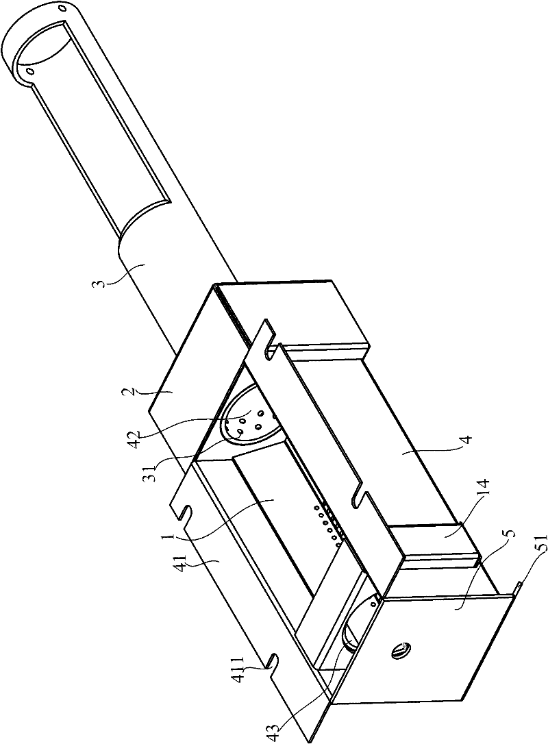
[0028] The embodiment of the invention discloses a combustion chamber, so that the fuel in the combustion chamber can be burned more fully, and at the same time, the ash produced by combustion can be discharged more conveniently.

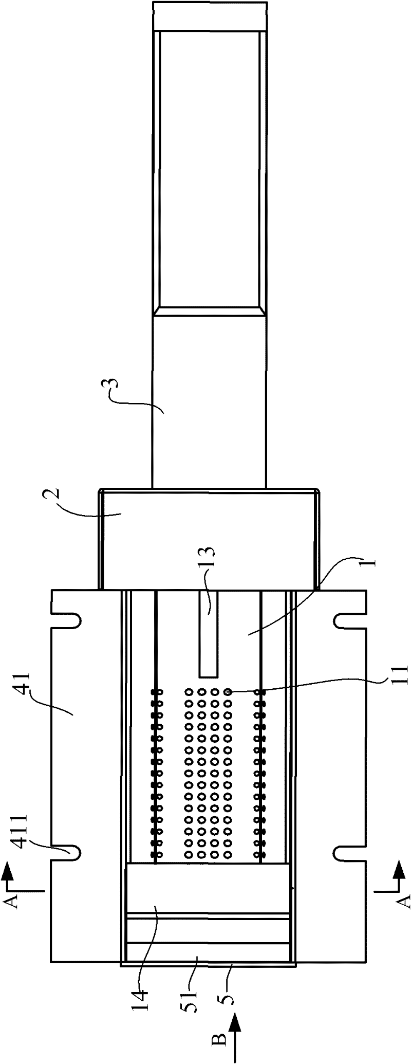
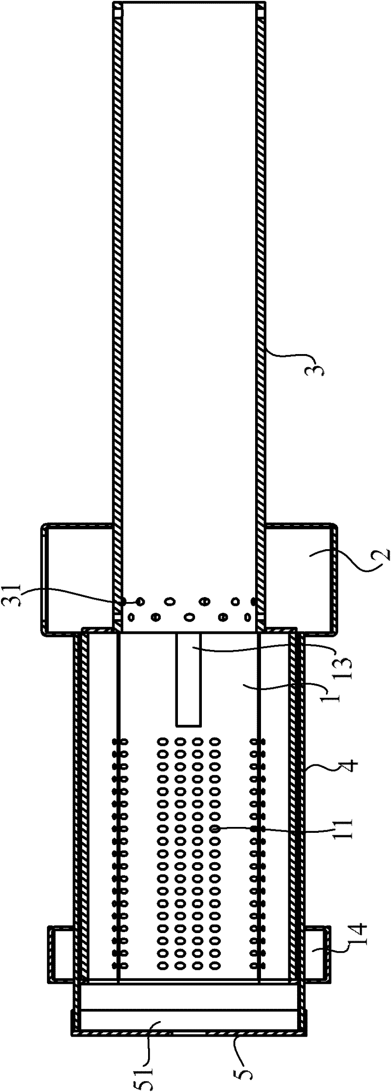
[0029] Please refer to the attached Figure 1-5 , figure 1 for figure 1 A schematic diagram of a three-dimensional structure of a combustion chamber provided by an embodiment of the present invention; figure 2 for ...


PUM


Abstract

The embodiment of the invention discloses a combustion chamber, which comprises a combustion chamber body, a combustion groove and an air inlet box, wherein a feed port is formed on an inner wall at one end of the combustion chamber body, and a deslagging port is formed on an inner wall at the other end; the combustion groove is sleeved with the combustion chamber body, two side surfaces of the combustion groove stretch upwards and outwards in the direction away from the bottom surface of the combustion groove, air inlet holes are arranged on the bottom surface and the two side surfaces of the combustion groove, a groove port of the combustion groove is communicated with the deslagging port, the feed port is positioned above the bottom surface of the combustion groove, and an air interlayer communicated with the air inlet holes is formed between the bottom surface of the combustion groove and the bottom surface of the combustion chamber body; and the air inlet box communicated with the air interlayer is arranged at one end, where the feed port of the combustion chamber body is located. The combustion chamber provided by the embodiment of the invention enable fuel to combust more fully, and simultaneously enable ash produced by the combustion to be discharged more conveniently.

Description

technical field [0001] The invention relates to the technical field of stove manufacturing, and more specifically, relates to a combustion chamber for a stove. Background technique [0002] Stove is the furniture commonly used in people's daily life. As the core component of the stove, the combustion chamber is the place where the fuel in the stove burns. The normal operation of the stove is realized through the combustion of the fuel in the combustion chamber. [0003] The air intake hole of the combustion chamber in the existing stove is arranged on the bottom surface of the combustion chamber, so that in the process of fuel combustion, the air is ventilated upward from the bottom of the fuel on the bottom surface of the combustion chamber, and the fuel is ignited under the action of the ignition rod to realize combustion. The air intake holes in the above-mentioned combustion chamber realize the mixing of fuel and air, but as the combustion proceeds, the ash and unburne...

Claims


Application Information

Patent Timeline
Patent Type & Authority Patents(China)
IPC IPC(8): F24B1/191
Inventor 朱宏锋王竹宏
Owner 朱宏锋
Why Eureka
Try Eureka