High-speed high-temperature multifunctional friction and abrasion tester
A friction and wear test, multi-functional technology, applied in the direction of testing wear resistance, measuring devices, instruments, etc., can solve the problem that the linear speed of the friction pair and the experimental temperature cannot reach high speed, and can not simulate the high speed and high temperature scratch wear of the turbojet engine. Working conditions and other problems, to achieve the effect of compact structure, low manufacturing cost and reliable movement
- Summary
- Abstract
- Description
- Claims
- Application Information
AI Technical Summary
Problems solved by technology
Method used
Image
Examples
Embodiment 1
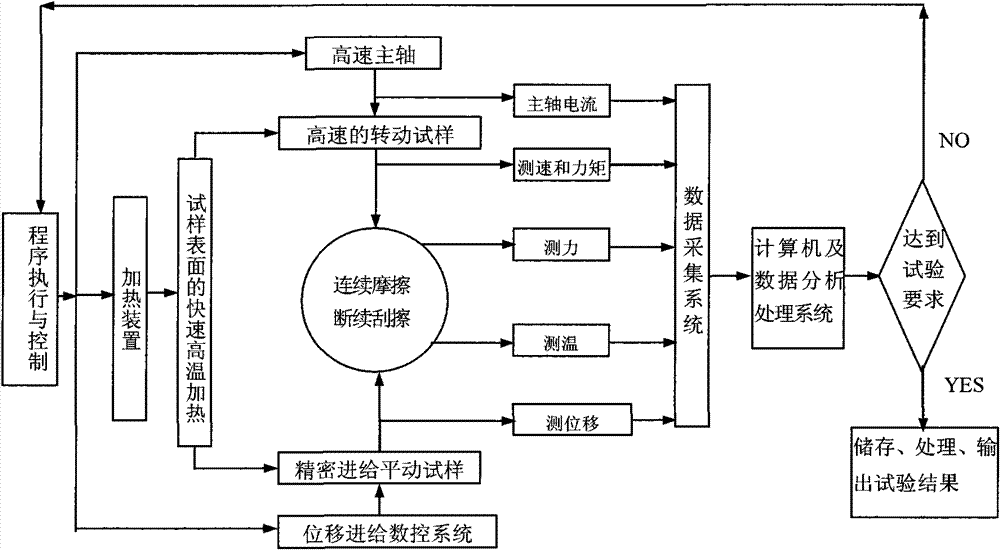
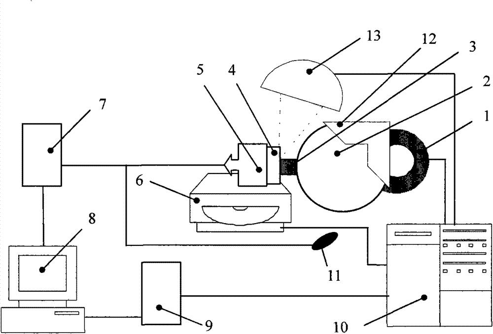
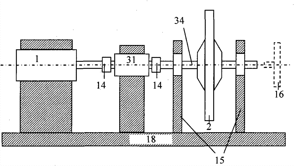
[0053] like Figure 5 As shown in the figure, when the scraping friction and wear experiment is carried out, the frequency conversion speed regulation parameters and acceleration curve of the electric spindle 1 are firstly used to achieve and control the spindle speed required by the experiment. Then, the torque meter 31 for measuring speed and torque is zero-adjusted, so that the no-load speed of the rotating sample reaches the conditions required by the stable test, and the torque value when not loaded is calibrated to zero. The rotating sample 3 is a single or multiple tooth-shaped scraping sample, which is installed on the rotating disk A2 on the rotating spindle 34, and its size and quality need to meet the static and dynamic balance conditions. The force measuring system 28 is arranged on one side of the longitudinal sliding table 27, the other side of the longitudinal sliding table 27 is a transverse sliding table 29, and the translational sample 4 is installed on the s...
Embodiment 2
[0056] The changes compared with Example 1 are:
[0057] like Image 6 As shown, the rotating sample 3 is installed on the outer circumference of the rotating disk B16 at one end of the high-speed rotating spindle 34, and the rotating disk A2 is separated from the rotating spindle 34 and fixed on the base seat 18. The rotating sample 3 is annular, and the outer diameter is smaller than the rotating diameter of the scratch experiment, which is beneficial to the preparation of the sample. Its outer circumference is the experimental surface, and it forms a ring / block friction pair with the block-shaped translational sample 4, and performs continuous or intermittent friction motion.
[0058] The process of conducting the friction and wear test of the ring block is as described in Example 1. In this embodiment, experimental parameters such as speed, temperature, feeding depth and feeding speed can also be actively changed to obtain various experimental schemes, including: adjustm...
Embodiment 3
[0060] The changes compared with Example 2 are:
[0061] like Figure 7As shown, the difference lies in the composition of the pin / disk friction pair, the translational sample 4 is pin-shaped and transformed into a feeding motion in the X-axis direction, and the annular rotating sample 3 is installed on the outer end face of the rotating disk B16 at one end of the rotating spindle 34, The outer end surface of the annular rotating sample 3 is the experimental surface, forming a circumferential wear scar track. At this time, in order to ensure the force balance of the rotating spindle 34, the position of the translational sample 4 must be symmetrical, so there is no movement in the Y-axis direction. The force measuring system 28 is arranged on the top of the longitudinal sliding table 27 , and the transverse sliding table 29 is arranged on the other side of the longitudinal sliding table 27 . Because the force measuring system is difficult to measure due to the balance of the ...
PUM
 Abstract
Description
Claims
Application Information
 - R&D
- Intellectual Property
- Life Sciences
- Materials
- Tech Scout
- Unparalleled Data Quality
- Higher Quality Content
- 60% Fewer Hallucinations
Browse by: Latest US Patents, China's latest patents, Technical Efficacy Thesaurus, Application Domain, Technology Topic, Popular Technical Reports.
© 2025 PatSnap. All rights reserved.Legal|Privacy policy|Modern Slavery Act Transparency Statement|Sitemap|About US| Contact US: help@patsnap.com


